About
What is it?
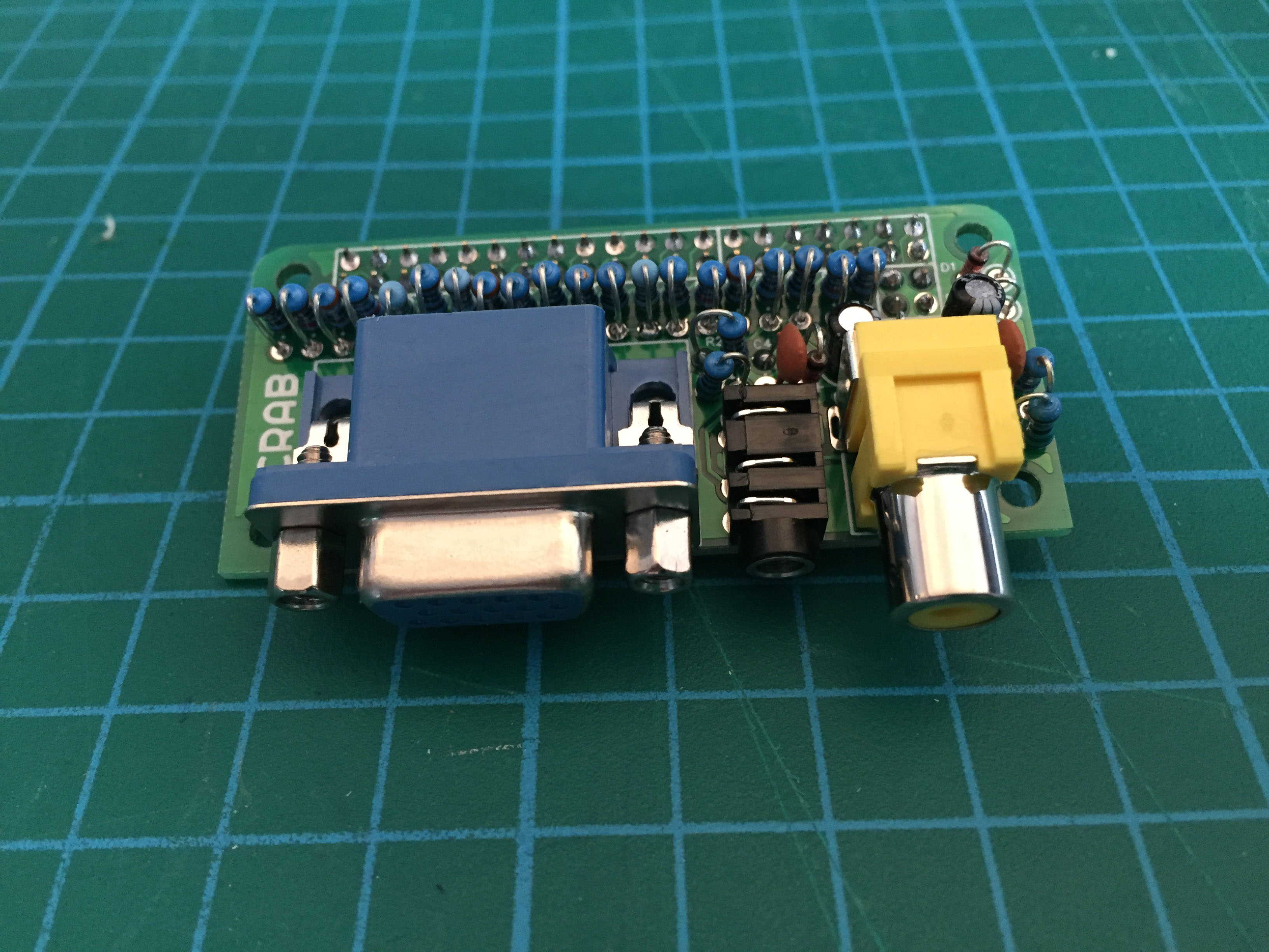
The analogue cap was designed in response to the release of the raspberry pi zero. For a low cost it helps to break out the analogue outputs from the zero. The analogue ports it provides are stereo audio, composite and VGA. All connectors are aligned to the same edge as the Zero's existing connectors. The board is ideal if you want to utilize a computer monitor, especially if it has built in speakers like many 'multimedia' TFT screens that now cost very little second hand.
Excluding the composite output it will also work on any Raspberry Pi that has the 40 pin GPIO header [ Raspberry Pi A/B+ and the Raspberry Pi B2 ]
It is a kit
To make it as cheap as possible and easy to adapt for different purposes it is a kit / bare PCB that uses only through-hole components. Due to a lack of space all components are folded this may make it a little fiddly to construct if you have less experience but it is not too hard. There will be full instructions on how to build the kit experienced and amateur alike in both document and video form.
What this means though is that you can choose which way up the cap is mounted, if you what the VGA or not and if you are building into an enclosure the pads can be directly soldered.
Bill of materials
| Type |
Value |
Designators |
Further Information |
| Resistors for VGA DAC (exclude if you dont want it) |
| 1% 0.25w axial resistor |
510R |
R1, R7, R13 |
|
| 1% 0.25w axial resistor |
1K |
R2, R8, R14 |
|
| 1% 0.25w axial resistor |
2K |
R3, R9, R15 |
|
| 1% 0.25w axial resistor |
3K9 |
R4, R10, R16 |
|
| 1% 0.25w axial resistor |
8K2 |
R5, R11, R17 |
|
| 1% 0.25w axial resistor |
16K |
R6, R12, R18 |
|
| 1% 0.25w axial resistor |
120R |
R19, R20 |
|
Resistors for audio |
| 1% 0.25w axial resistor |
270R |
R21, R22 |
|
| 1% 0.25w axial resistor |
150R |
R23, R24 |
|
| Capacitors and Diodes |
| Ceramic Capacitor |
47n |
C1, C2 |
|
| 5mm Electrolytic Capacitor |
10uF |
C1, C2 |
|
| Schottky Diode |
BAT42 |
D1, D2, D3, D4 |
|
| Connectors |
| 40 Way socket |
2x20 2.54mm |
|
|
| 4 Way socket |
2x2 2.54mm |
|
|
| RCA socket |
|
Composite video out |
|
| 3.5mm TRS socket |
|
Stereo audio out |
Rapid Electronics |
| VGA female socket |
15 way D-sub (DE-15) |
VGA video |
|
Files
All CAD files and documents are available to download and use for free, licenced under GNU GPL. The latest files can be found in the Github Repository
- Diptrace Layout : Source files for the board layout and schematic
- Gerber Files : Files you can send to for manufacture
- Bitmap Files : Files you can etch yourself (note its double sided so can be quite difficult to align)
Build Instructions
These instructions are to help you if you are unsure how to put together this kit. If you have assembled a board and are confident the board is clearly marked so it should be pretty simple to assemble with just the Bill of Materials (BOM). I can give you no warranty that you will end up with a working board at the end but I hope it is easy enough that it should work. If this is your first time you have assembled a PCB just take your time and double check everything as you go along, especially check before soldering as you are commiting the component to its position and it can be hard to remove a component if you lack experience.
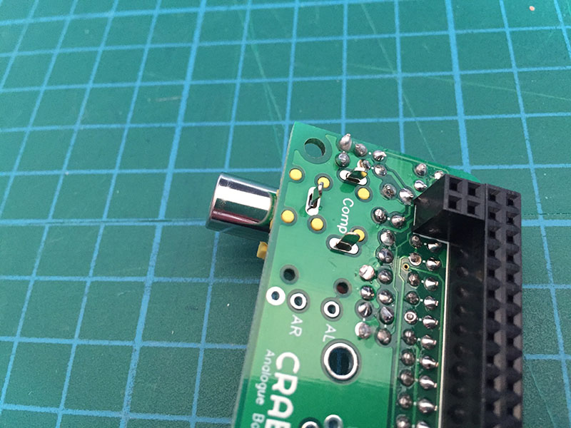
Please note these instructions were made with a protoype board so it looks a little different; there are big holes drilled in the VGA footprint(fixing an error). But fundamentally all parts are in the same place apart from R19 and R20 which swaped places next to eachother
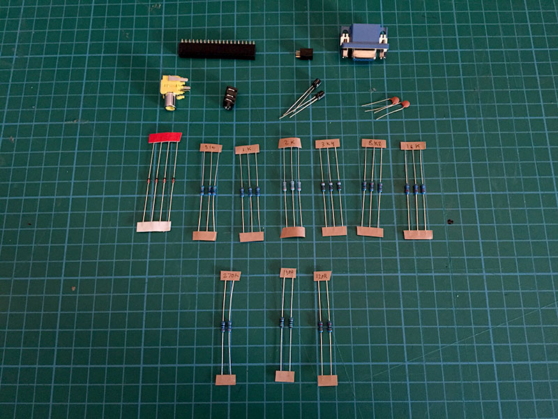
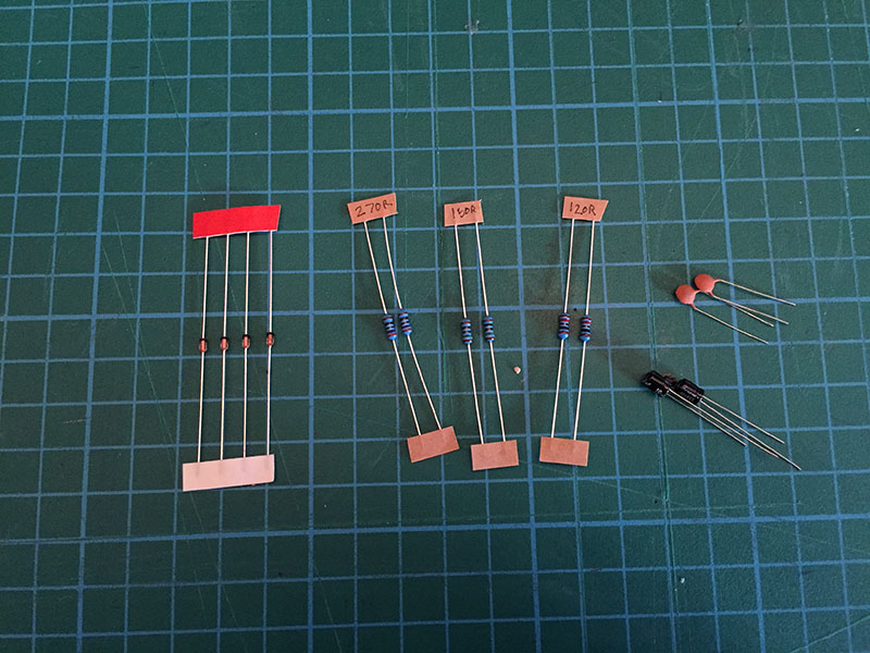
First make sure you have all the components, you should have all the parts listed above. Lay them all out and double check as it is quite easy to lose them. There should be an included BOM on a small card, or use the list on this page to check
Step 1
If you do not wish to solder on the VGA then leave this part out and skip to step 3
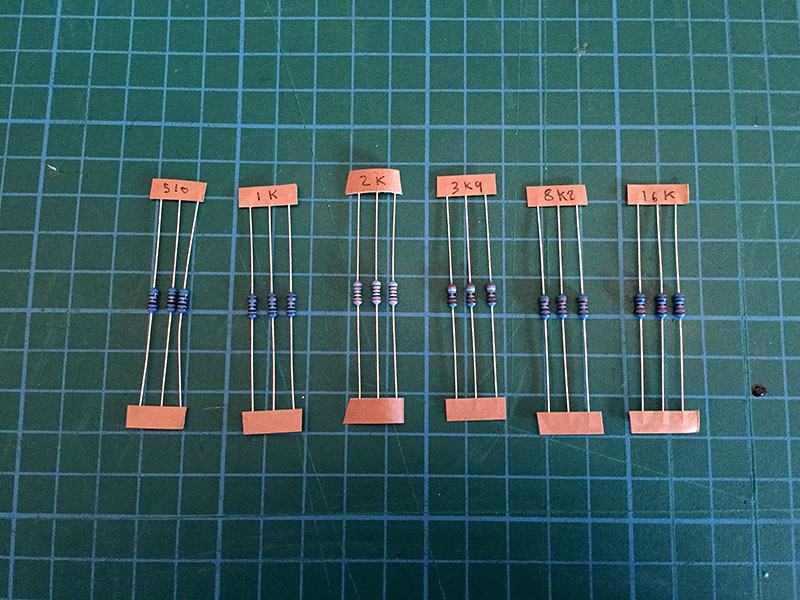
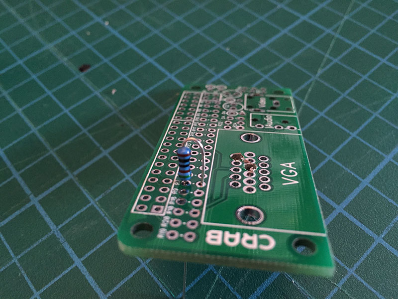
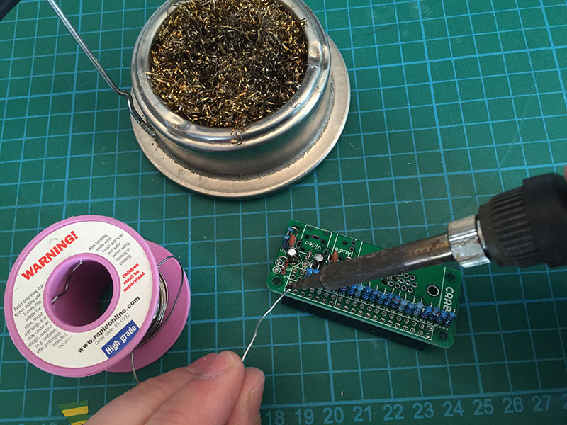
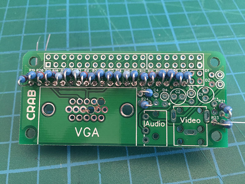
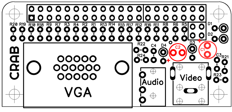
The best way to assemble it is to start with the resistors as they are harder to put in once other components are on the board. Select resistors R1 to R18 as pictured, these are the digital to analogue resistors that convert the signal for VGA. We will first place all these resistors in and solder them at once.
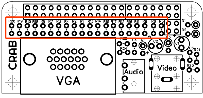
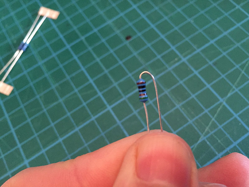
The DAC resistor section is highlighted above, R1 to R18 are located here. The value of the resistor is marked by its colour banding. First we should start with R1, R7, and R13 which is the value 510R they need to be placed into the holes where their designator is marked.
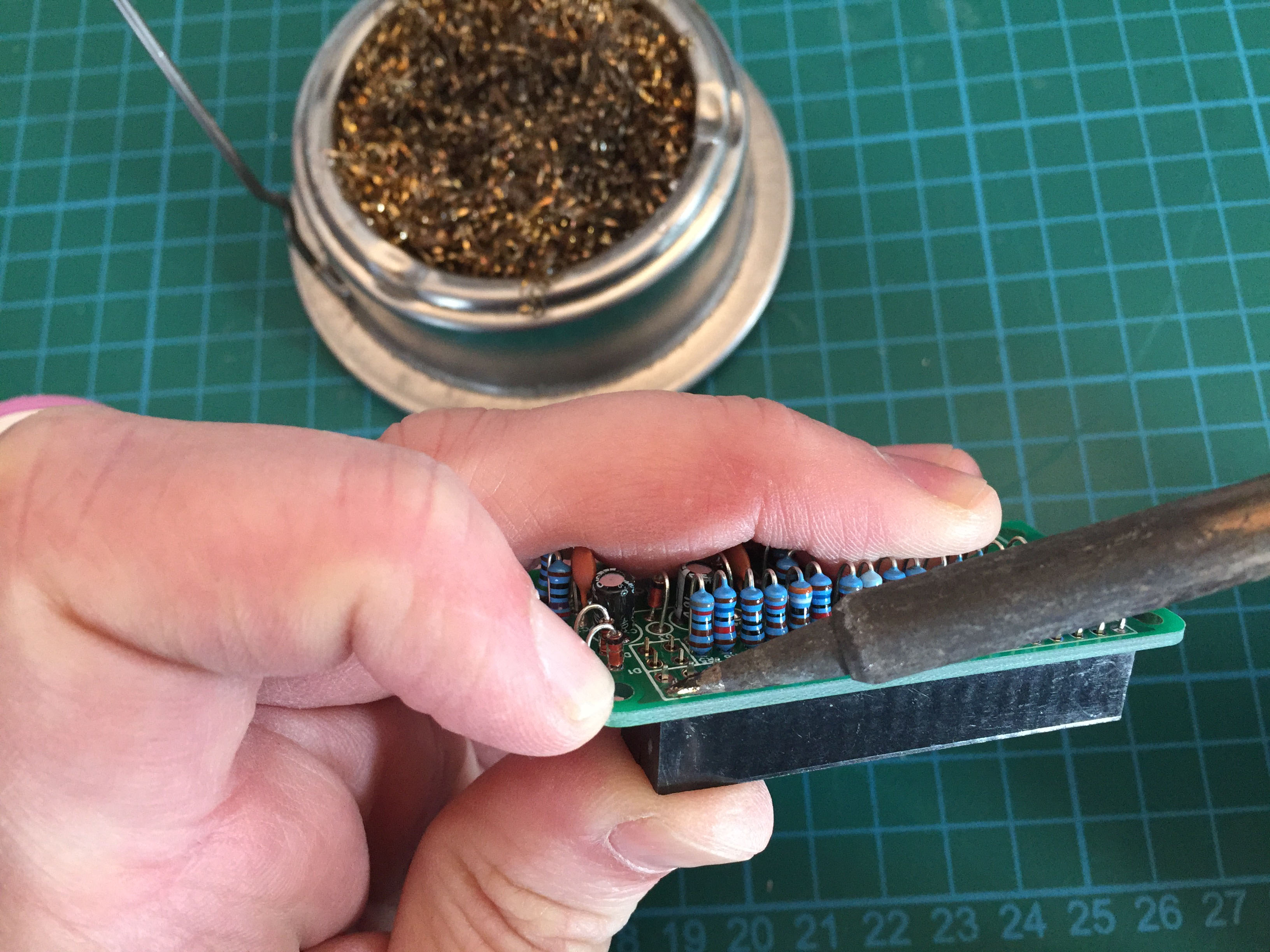
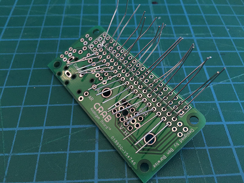
Bend the resistor as shown, it does not matter which way around the resistor goes and then place into the hole as shown. Bend the wires outwards underneath so that it holds itself in place, do this for all 3 resistors.
Make sure that you bend them underneath so that the resistor holds in tight and does not fall out
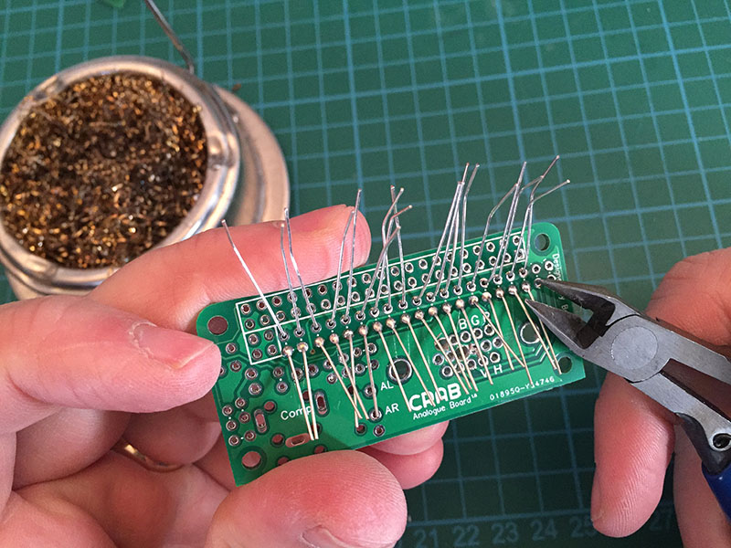
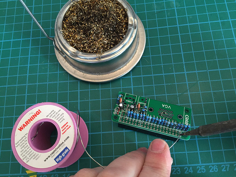
Then move onto the next three (1k) then 3 x 2k, 3 x 3k9, 3 x 8k2 and 16k. Dont solder anything until you have put all the resistors in because it is very easy to get them the wrong way around.
Double check if not quadrouple check you have all the resistors in the right place. If you solder them into the wrong place you may have trouble fixing it!
Step 2
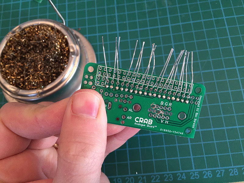
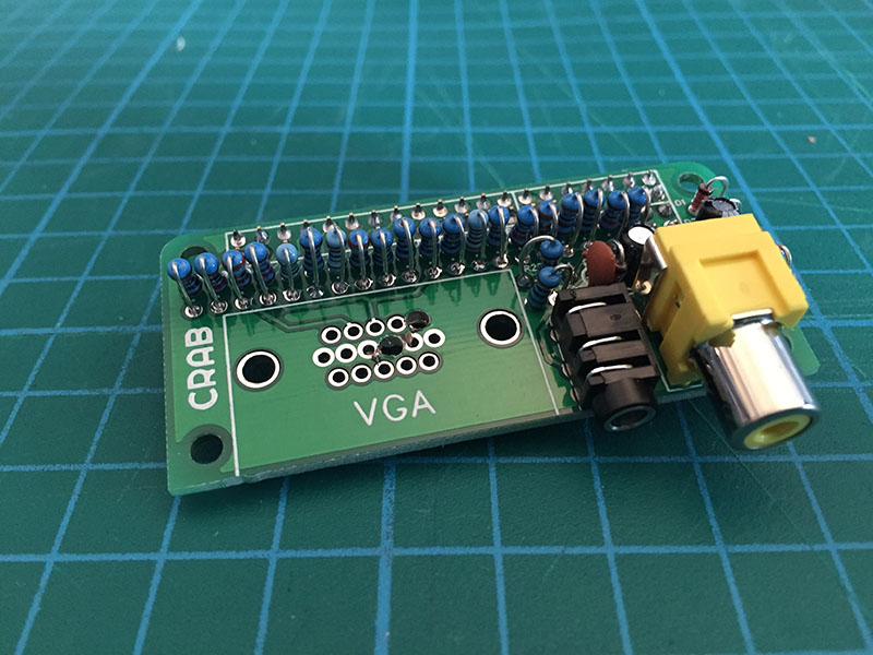
It should now look like this, now we will solder these down and the DAC is done!
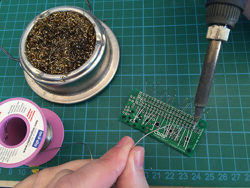
Turn on your soldering iron wait for it to heat up properly, you can test it by melting a little bit of solder on the tip (wipe it off though!), it should only take 5 mins max. Use a wet sponge or metal bush as I have to clean the tip. The soldering tip should have a metalic shine to it, this is the point that you should soldering with. If the iron tip is dull grey and when you put solder on it it just balls and falls of you will have trouble soldering with it. It is difficult to descripe how to fix this, but it may be best to get a new tip or alternate soldering iron.
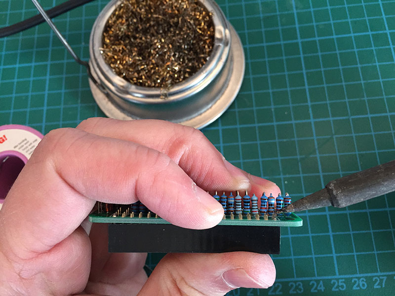
Flip over the board and place the soldering iron tip onto the lower left pad as pictured. You want to press the iron gently against the wire and the pad. Then feed in a small amount of solder, it should seem to suck into the pad the move on to the lower one next to it.
Repeat for all the lower pads and then using the snips cut all the lower pads off. Now rotate the board so the unsoldered wires are downwards and repeat the same soldering and snipping. It should look like this.
Step 3
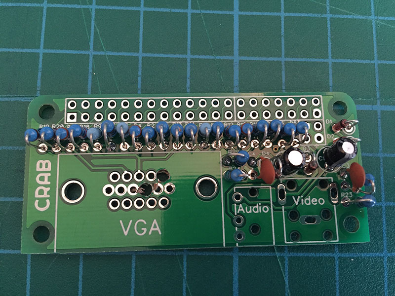
There are 6 remaining resistors, in 3 values and 4 capacitors in 2 values, check them against the BOM. The resistors are soldered in the same way as the DAC and the capacitors should not need their wires bent to fit the holes.
For the H-sync and V-sync there is R19 and R20 highlighted in the picture. Skip these out if you do not want to solder in VGA.
For audio there is R21 and R22 which is 270R solder them into their respective places (use picture below as guide) Then also for audio is R23 and R24 solder them the same way too. remeber to check you have the right holes!
Step 4
Now is the capacitors, the small brown ones are not polarised this means they can go in either way but the black ones are polarised so be careful with their orientation.
First put in and solder C3 and C4
Now put in C1 and C2, the white section with a '-' marked on it as shown is the negative so the other wire is positive. There is a small '+' symbol on the board to show wich way around it is installed. Solder them in.
Finally we need to put in the protective diodes for the audio jack, these are polarised. Because of limited space I could not mark the diodes orientation as a line. So instead the orientation is marked with a circle around one pad. On the diode you should see a black stripe, the black stripe end should go into the pad with the circle. Be careful here if it is the wrong way around the audio will not work.
Step 5
Now for the connectors! there are 5 of them each serving a different analogue output. They are all completely optional even the 40 way socket, you could directly the board directly to the raspberry pi header (but that would severly limit its use!). Or if you were building this into a device you could solder connectors from a panel to the socket footprints, its up to you! for best flexibility just use the connectors.
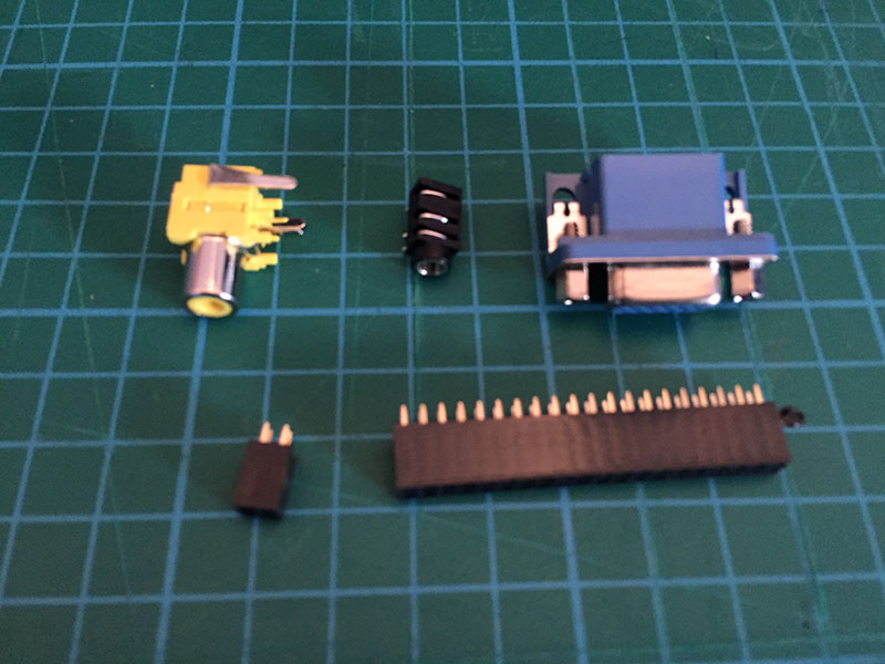
We will start with the hardest first, the socket to connect to the Pi. It does not have an orienation.
I find the best way to do this is to place it in and solder one pin at each end. Then hold up the board and see if the connector is flush with the board, if it is not use the soldering iron to melt the pad and you can push it flat as shown. Dont touch the pins you are soldering! Then solder every single pin down (yes all 40!)
Repeat for the smaller 4 way pin, it should fit in perfectly next to it.
Step 6
Now push in the connectors you need, the composite and VGA connectors should click in and be flush with the board as shown. The 3.5mm jack may not hold it so well so use the same method as in step 6 by soldering one pin first to get its position against the board then solder all the others.
Solder all the pins of the connectors on the VGA solder the 2 clips too, this makes it mechanically stronger for the bulky VGA.
Step 7
If you are using a Raspberry Pi Zero and it has no header, you should now solder in the included header, use the same method as step 6 taking care not to touch the pin you are soldering.
Next you need to configure the Raspberry Pi image for VGA see the instructions for that.
Installation Instructions
Easy Way
Download the 2 files found here
Insert the Raspberry Pi SD card into your PC and copy 'config.txt' to boot and 'crab-vga-overlay.dtb' to boot/overlays
Unmount and put in Raspberry Pi, it should boot to XVGA resolution
Better Way
Only better because if you have settings in your config.txt file they do not get overwritten. Also you can select what options you want and which you don't
Download 'crab-vga-overlay.dtb' found here
Either copy 'crab-vga-overlay.dtb' onto the SD card under /boot/overlays through your PC or use wget to download it from the Pi (use this link)
Edit config.txt and add the following lines. Note that each section is optional they do not have to all be on at the same time.
VGA
# Enable pins to be DPI output
dtoverlay=crab-vga
enable_dpi_lcd=1
# pin arrangement that works with this cap
dpi_output_format=6
# Make this display default output (if not set HDMI will show shell and VGA screen will be blank but work)
display_default_lcd=1
# Set resolution of VGA (numbers the the same as HDMI)
dpi_group=2
dpi_mode=16
Audio
# Enable audio
dtoverlay=pwm-2chan
Composite
# Settings SDTV (composite) this is set to PAL btw see here for settings
sdtv_mode=2
sdtv_aspect=2
# Overscan settings
overscan_left=16
overscan_right=16
overscan_top=16
overscan_bottom=16
Troubleshooting
Coming Soon