BUILD YOUR OWN MODULAR
Back to main to BYOM pageDETAILED ENCLOSURE ASSEMBLY INSTRUCTIONS
This page is dedicated to detailed photographic step-by-step instructions for the assembly of the BYOM enclosure in the BYOM kit.
ASSEMBLY
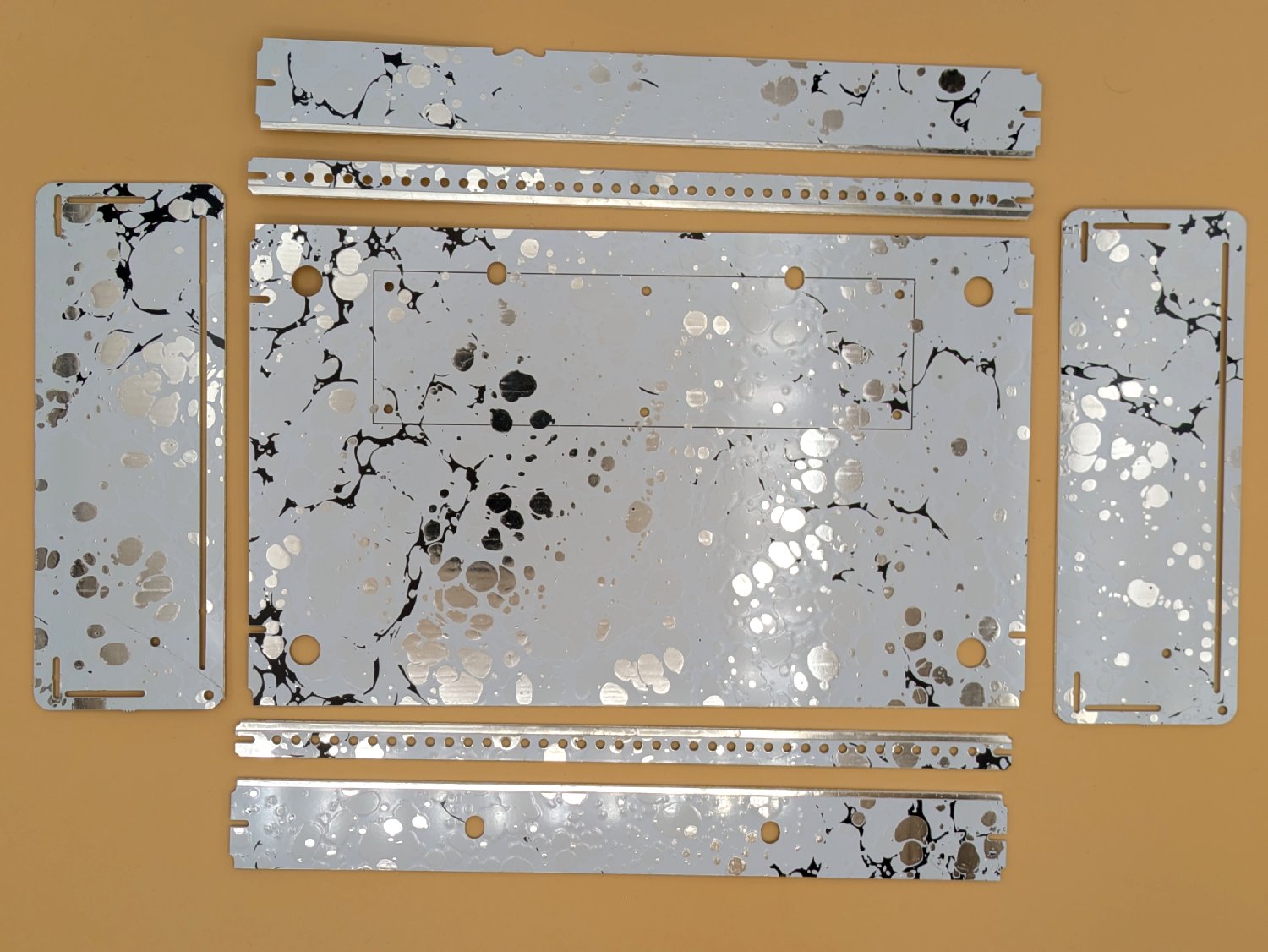
There are two cases per book, there are two different pages that are used to make one enclosure. Break apart the pieces until you get the following parts. 2 rails, 2 support rails, 2 cheeks and a base. You have to bend the parts back and forth to get them apart, it can be a bit tough. Use pliers and run them up and down bending carefully.
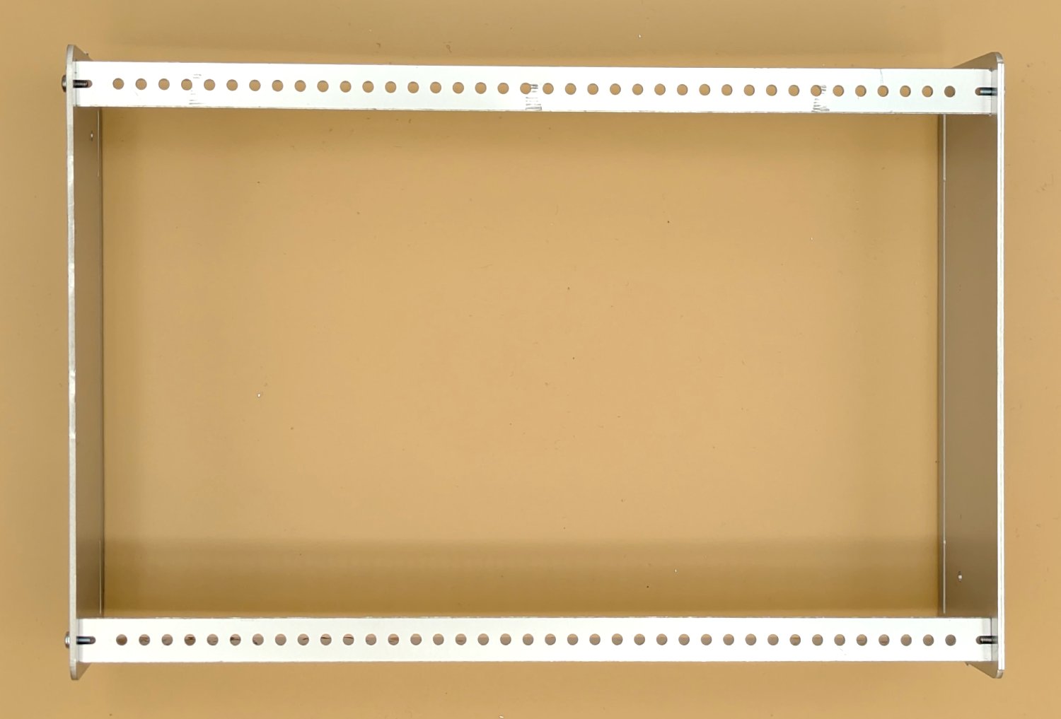
STEP 1 : BUILD THE FRAME
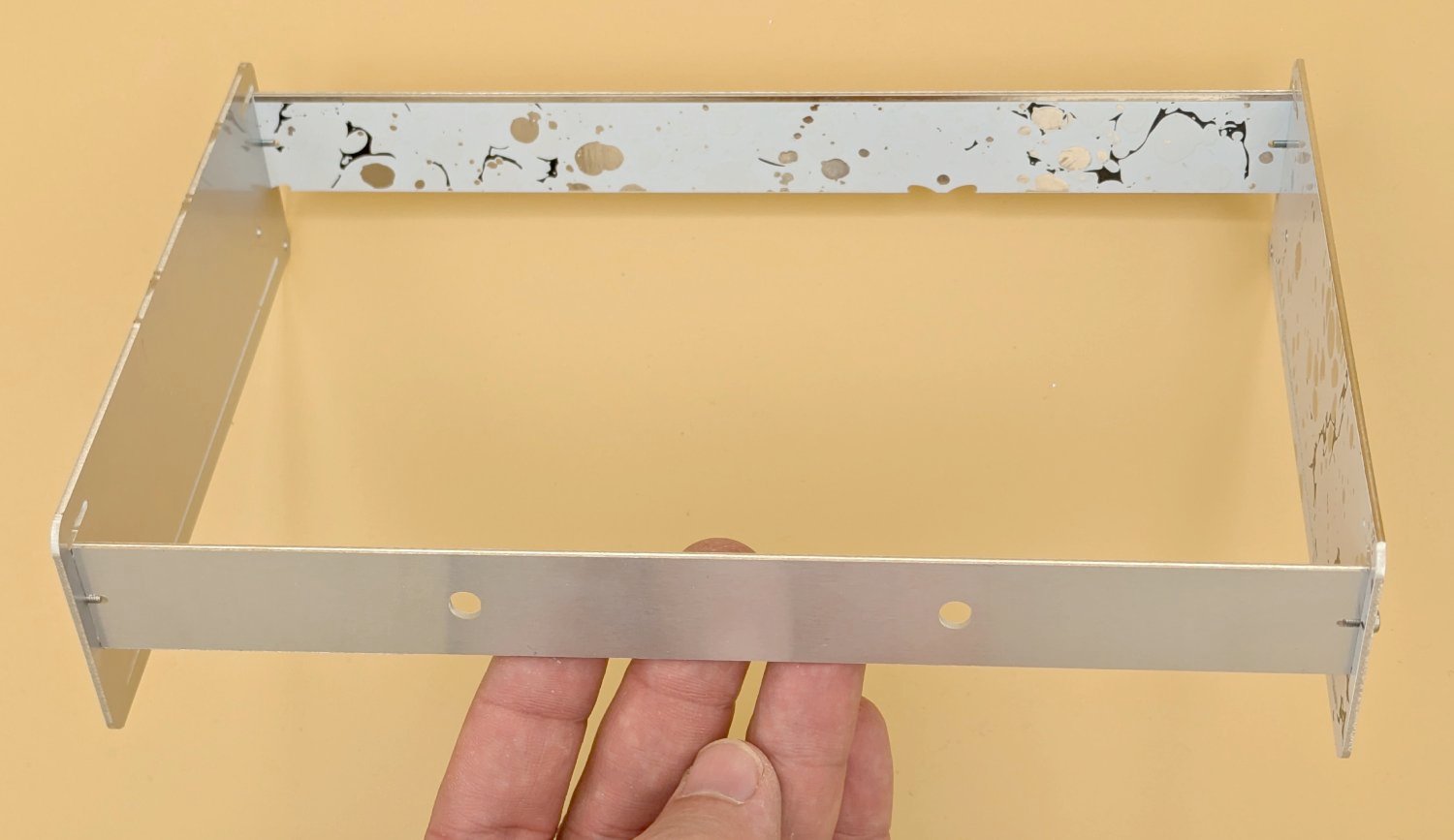
Use the M2x4mm screws to put together the cheeks and the support rails, they should self-tap into the hole. Don't put the screw in then push in the rail, put in the rail and then screw in the bolt. This is because the bolt has to center to the hole and needs both the slot and the hole to align up. The silver strip of the support rail has to face upwards as this is soldered onto the mounting rails, you can see it in the photo. Note I accidentally put one of the cheeks the wrong way around in this picture, but this shows you can actually choose which way around the cheeks are, they can be silver or patterned on the outside. The support rails have to have the pattern inwards as we will be soldering it to the rails. Take care screwing not to over tighten the bolts as they will shred the hole if done too tight.
STEP 2 : INSERT THE MOUNTING RAILS
These are the strips that the modules screw into, they are very flexible and thin but they will gain strength when they are soldered onto the supporting rails. You can slide them in from the side or bend them in on the front. Make sure the silver strip on the patterned side matches with the silver strip of the support rail, these two strips are going to be soldered to each other.
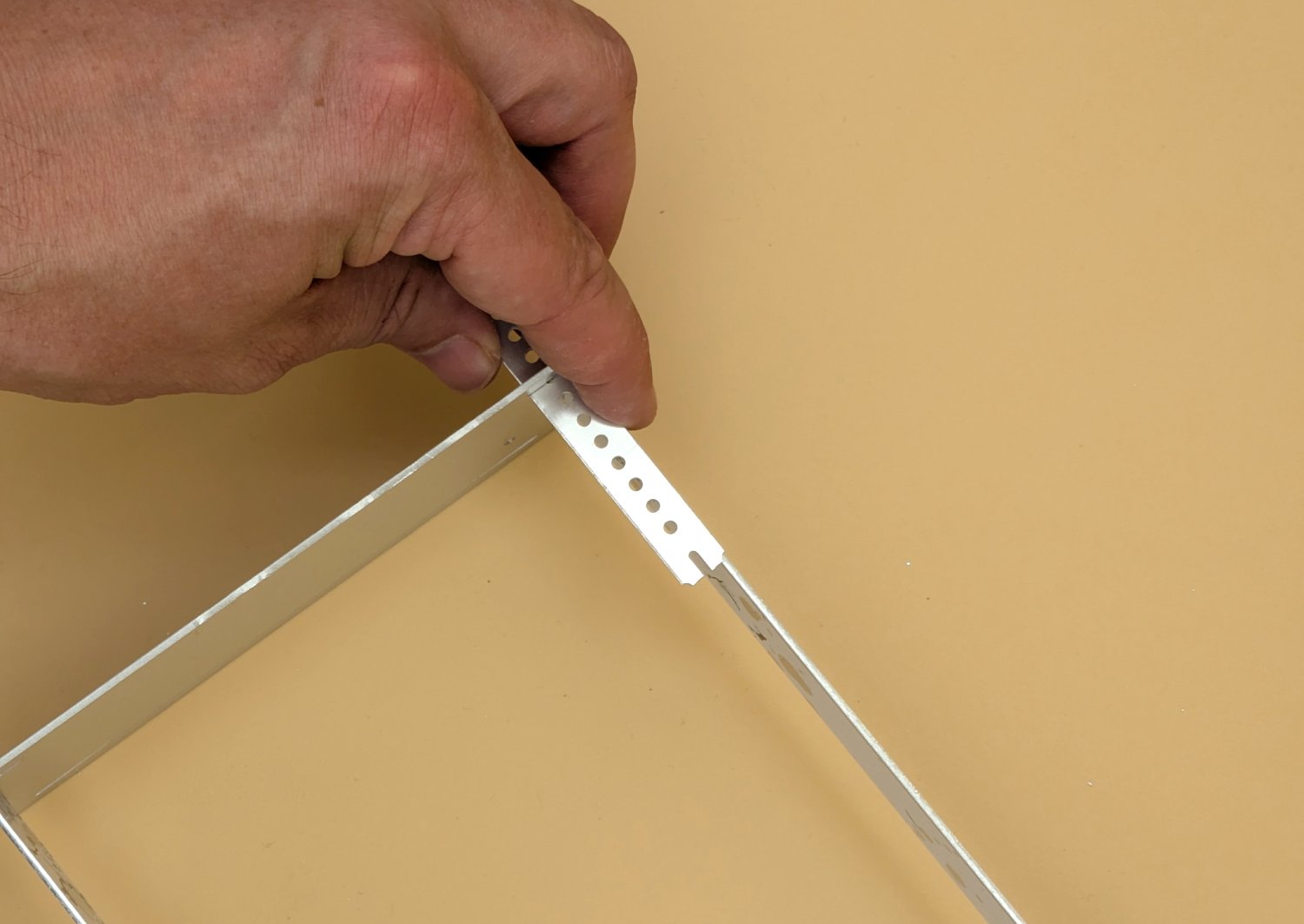
Then screw them in at the sides, try and make it as flat as possible, but again don't go over the top tightening them as it can shred the thread of the hole.
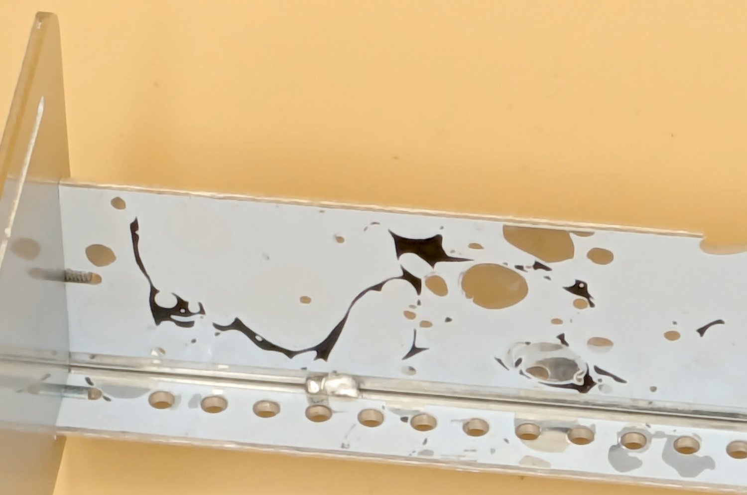
STEP 3 : SOLDER TAB THE RAILS
Put the case upside down and solder tab the rail to the supporting rail. Place something heat proof under the rail so that it pushes into the support rail. Turn your iron up as hot as you can get it, a tip is to heat it for ages before you start to feed in the solder, the opposite of what you are told when soldering in components! Wiggle the iron around to try and encourage the solder onto the silver strip. You may find your iron can not get the solder to melt, but just persist and try the best you can. It doesn't have to be beautiful, it just has to be connected.
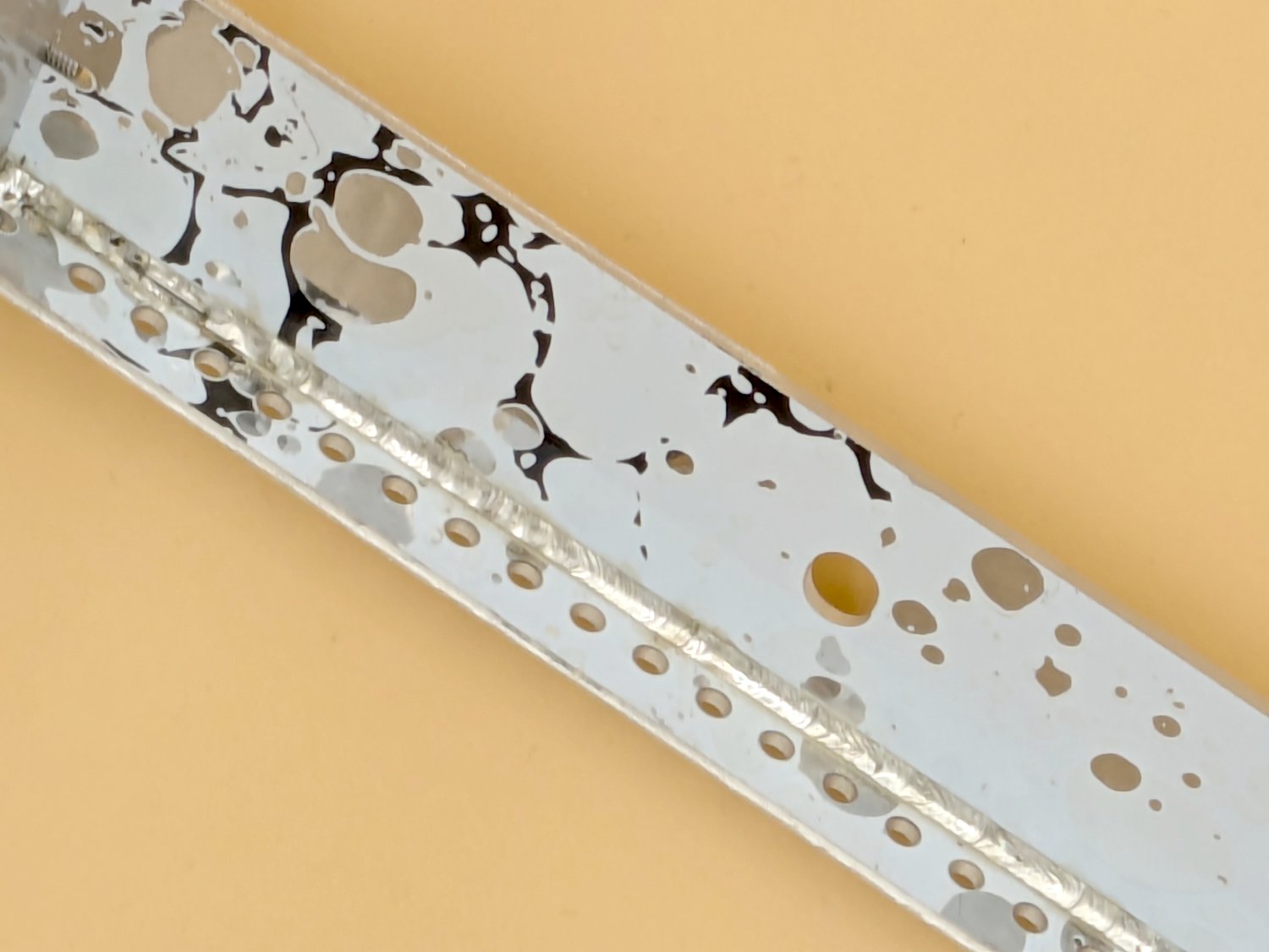
If your iron solders well, I like to do a sort of complete weld along the entire strip. I struggled to get an action shot, but you have to pull the iron along the strip towards you and feed in the solder as you go along between the gap in-between your iron and the strip at the front. It makes this cool looking weld like effect. But this is not necessary you can skip this step if your iron does not have the heat transfer capability, e.g a 25W iron.
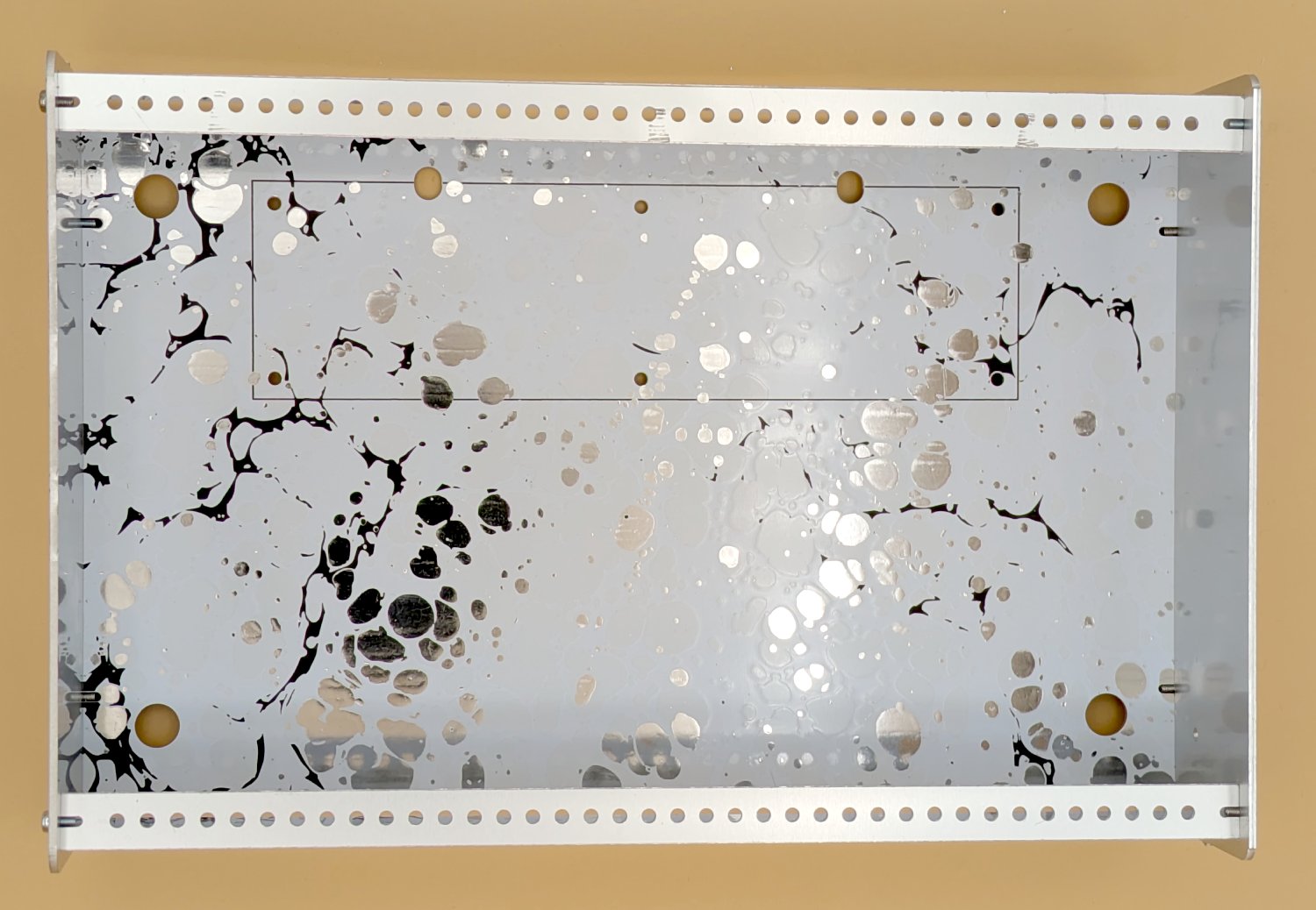
STEP 4 : PUT ON THE BOTTOM
The bottom part should just fit in the slots, the case should be quite rigid now. Gently flex the cheek panels to get the bottom panel in, it attaches with 4 M2x4mm screws like the rest of the case. Again you can choose to have the inside silver or patented it doesn't matter, just an aesthetic choice. You now have the enclosure frame complete!
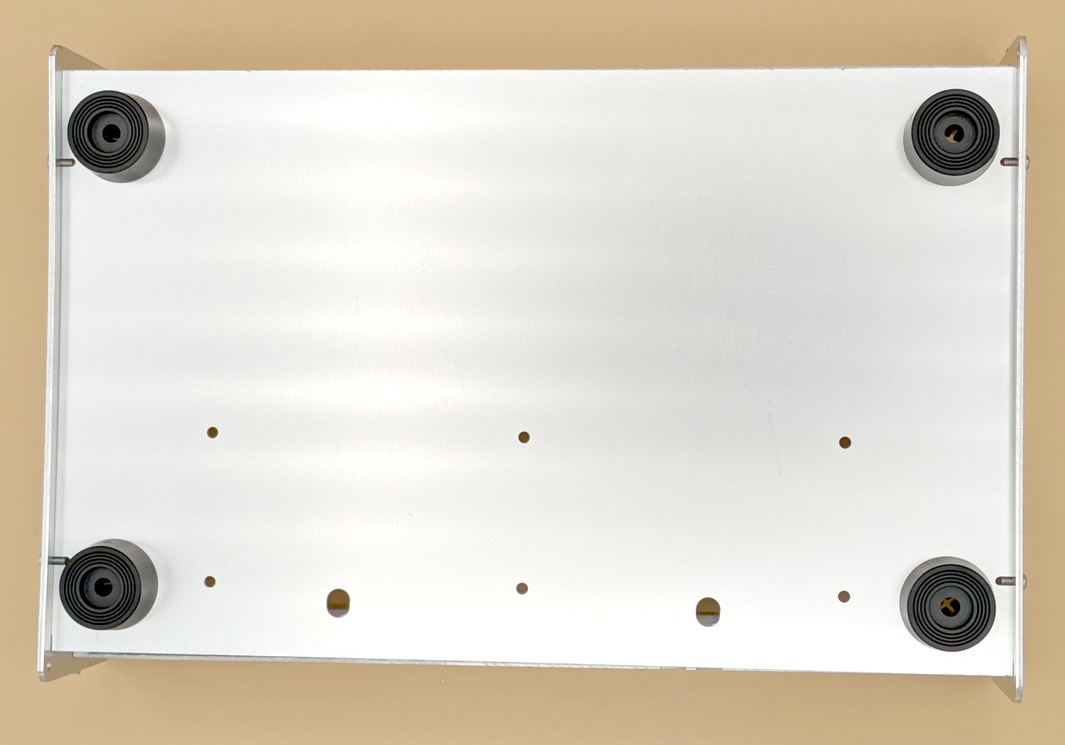
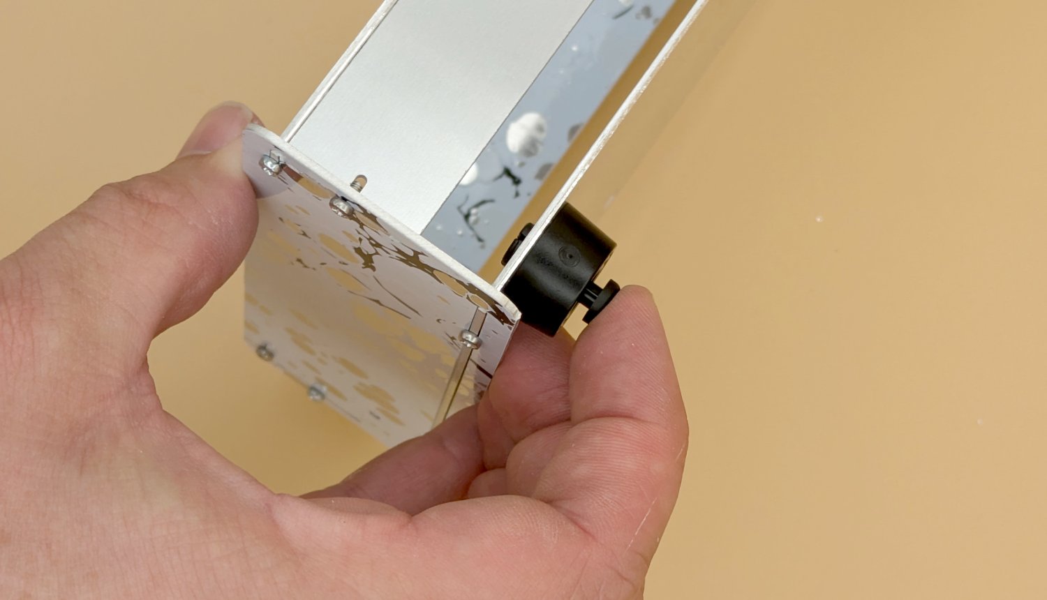
STEP 5 : FEET
The feet push into the 4 large holes on the bottom and then there is a small plastic insert that holds the foot in.
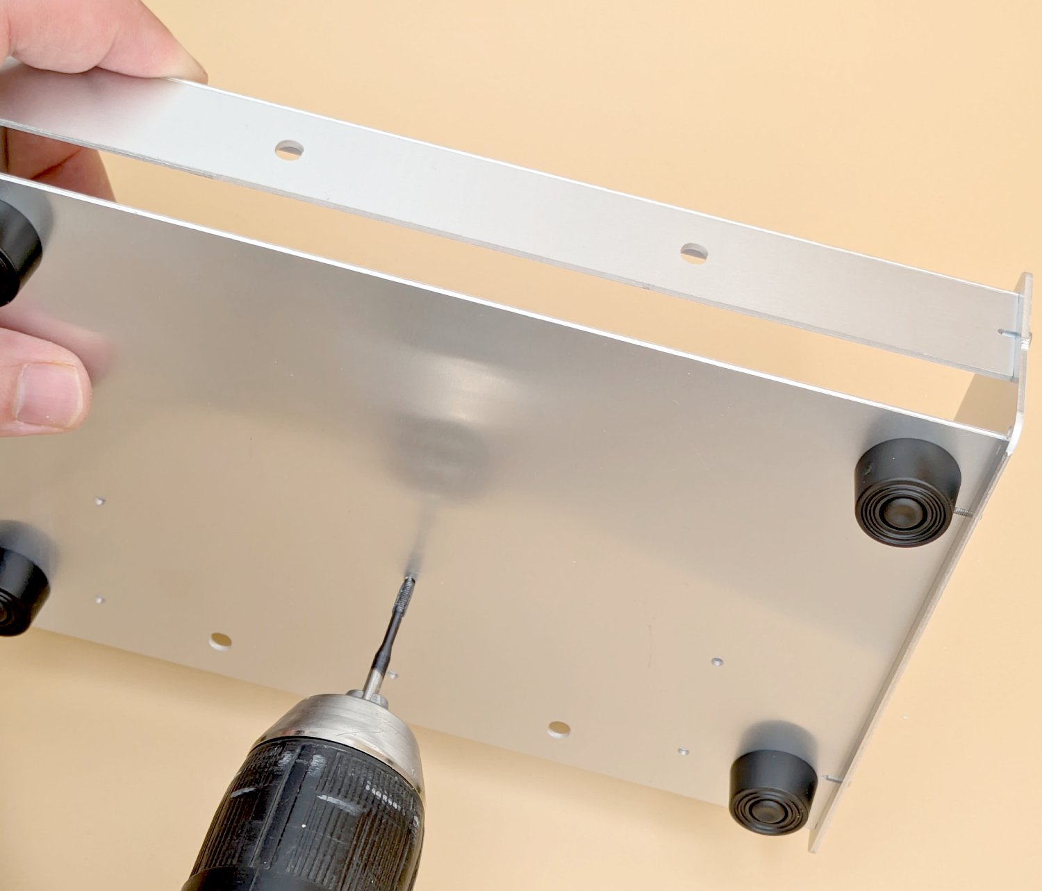
STEP 6 : TAP HOLES
Tapping is fairly tricky especially with a hand tool. We are going to tap the 6 holes on the bottom panel. This is the best place to start because if you mess any of these holes up it actually doesn't matter because they have bolts on the other side anyway. So these 6 holes are essentially your practice before commiting to the holes on the top which have to work! Put some oil on your tapping tool and then hold it 90 degrees to the hole. Start turning the tool and gently apply pressure. Screw it all the way in past the taper of the tool, allow the tool to guide the rate at which it is feeding into the hole as it is cutting a thread! When you are far enough, reverse the rotation until the tool comes out the hole. I use a drill for speed and I find that it makes better holes because there is less wobble from your hand trying to rotate the bit.
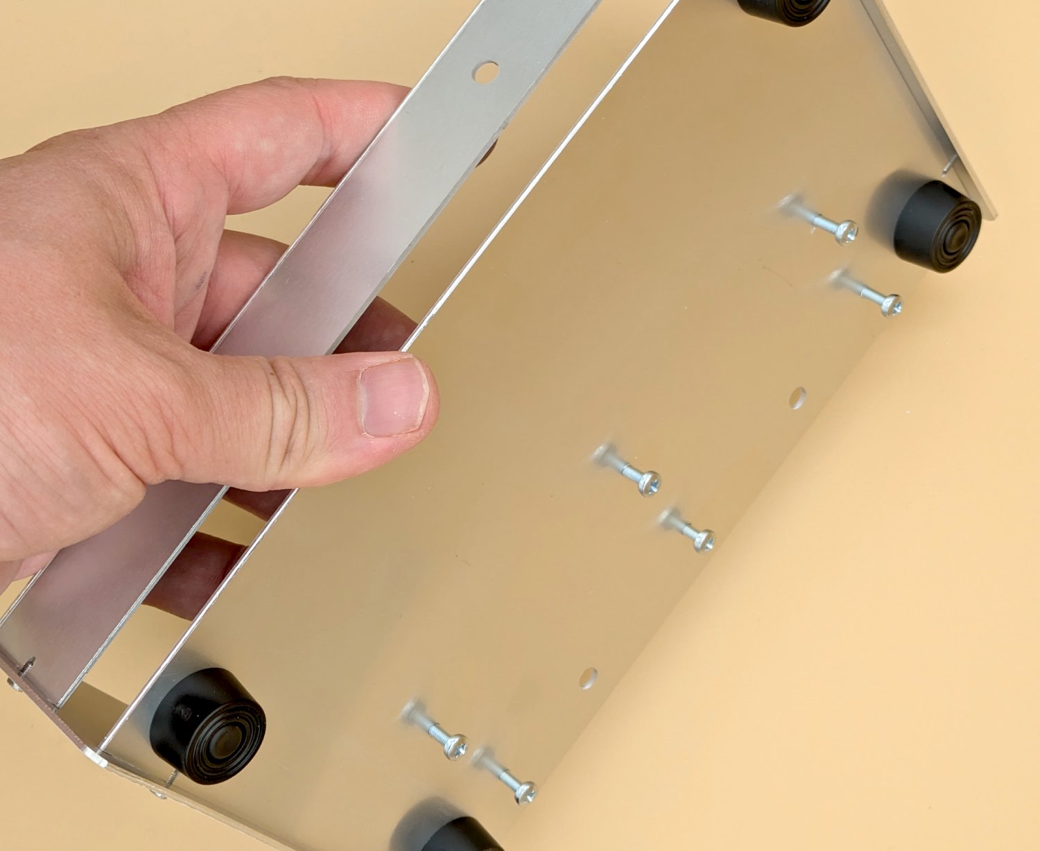
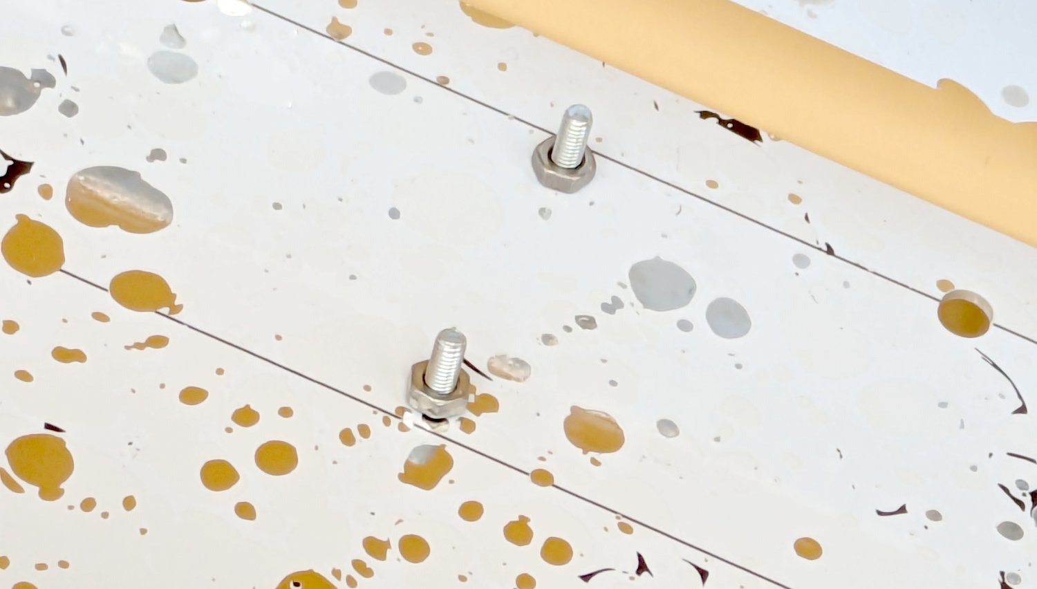
STEP 7 : INSERT SCREWS
Now put in the screws, they should be M3x8mm or M3x10mm. As it is a threaded hole they should go in nicely. Don't tighten to hard of course.
STEP 8 : NUT SPACERS
Now put the M3 nuts onto the bolts on the other side, they hold the Bus PCB away from the surface to prevent shorts. Tighten them with some pliers or a wrench/spanner if you have one.
STEP 9 : BUS PCB
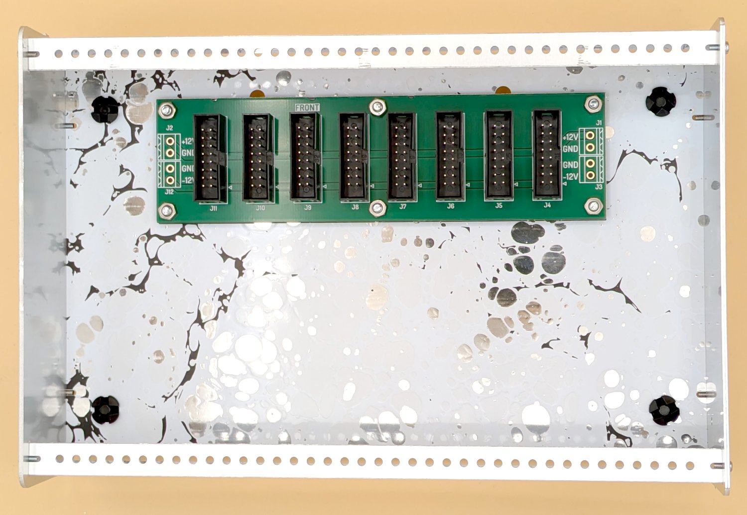
The bus PCB is provided at the bottom of two of the green PCB dividers in the book. They just need the 8 of the 16 pin IDC connectors soldered to them. This is a lot of soldering so take your time and check for shorts. Make sure you solder onto the "FRONT" of the PCB and watch the orientation of the connectors. You can fit all the connectors at once and then use another PCB to sandwich it together and flip the board upside down for soldering.
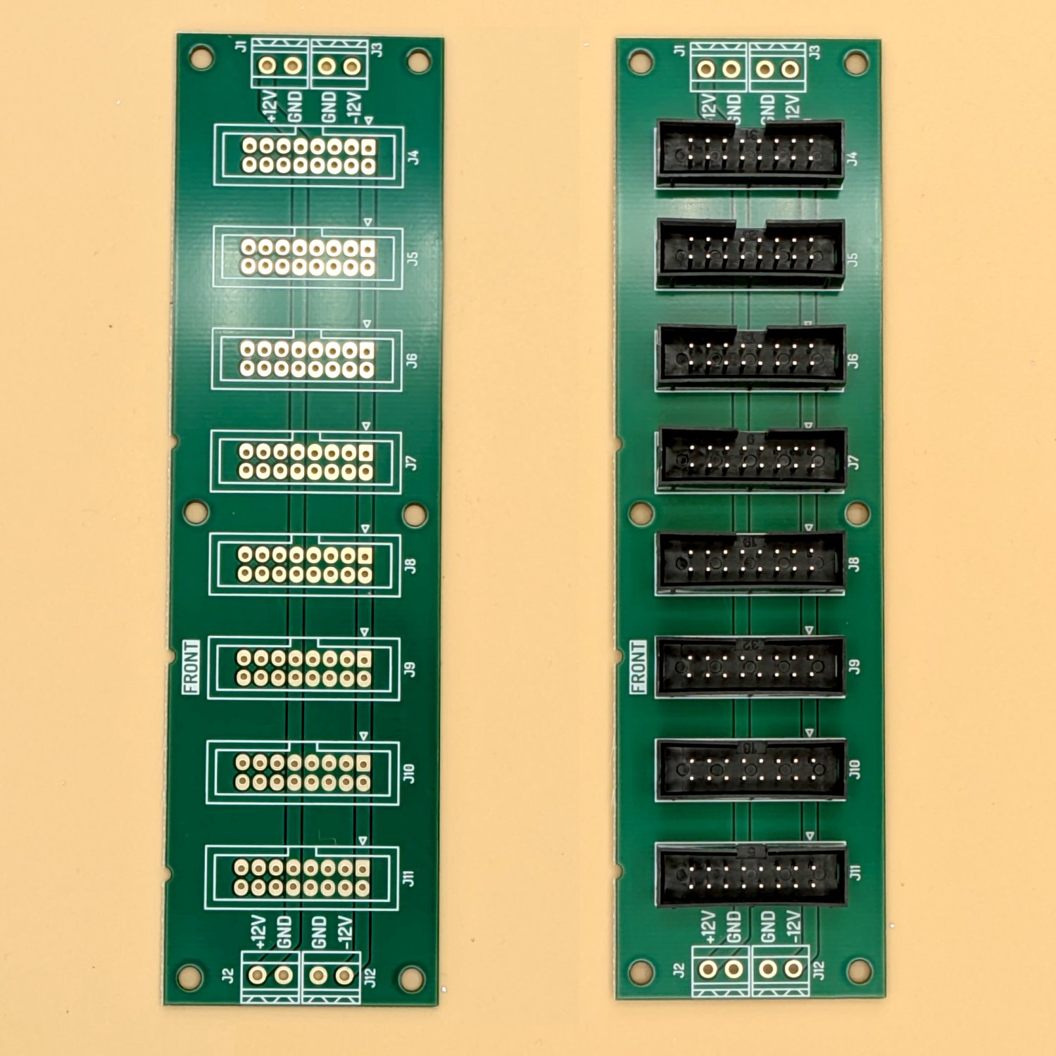
There is nothing else needed for this PCB, the power connects in and comes out of the PCB using the IDC connectors alone
STEP 10 : MOUNT PCB, FINISHED!
Now place the PCB into the case and use a further 6 M3 nuts to fix the PCB in place, you are now finished.... but you still have to build another one!