Colours, Speakers and Pulses
 This is a story about what I currently do, I have moved a little bit away from synthesizers but still make audio electronics for artist Haroon Mirza and sometimes other artists. The approach to making artworks are different to designing audio devices, as usually components and circuits are one-off designs or modified items which are usually used against their original intention. The reason I decided to write about this was to document how the system works for this particular work as it is using new technologies that are getting easier to prototype with. I am really impressed with this new microcontroller implementation of Python programming language called Micro Python.
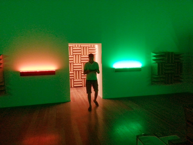
Courtesy the Tinguely Museum, Switzerland
##Background
Channa Horowitz . was an American artist who came up with a system called ‘Sonakinatography’ which is a compound word of sound, motion and notation. According to Wikipedia the system was part of a proposal for a sculpture that she sadly never got to produce, she did produce drawings for the works and although they are scores for works they actually became ‘artworks’.
I am not sure if I am allowed to post a photo of an artwork but if you search Sonakinatography in your favourite search engine you will see the drawings. The way the work was interpreted is that each horizontal line of Channa Horowitz’s work is treated as a step, like a step sequencer this is fed to 8 RGB LED strips that each sit on top of a 3 channel sound bar (the speakers for TVs). The PWM control of the Red, Green and Blue is also fed into the 3 internal speaker cones od the sound bar ; so left speaker is red, middle green and right is blue.
##Better Specs
For ages we had been using Arduinos and burning PICs to playback sequences but they had hit memory limits. This was temporarily helped by storing sequences as byte arrays (smaller than integers) and using an Arduino Mega with larger flash memory but as longer and longer sequences were used the devices kept running out of space. Channa Horowitz’s work is up to 4000 lines so this would definitely overflow the memory! The only solution for this was to use external memory, ideally I thought was to use a memory card to make it easier to change sequences.
There also was a new requirement, for this new work it needed to drive 8 x RGB leds this means we would need a device to output 24 independent channels this is beyond the Arduino Mega alone. At first I investigated using serial controlled PWM devices such as the SPI controlled TLC5947 but a requirement was that each channel could have its own pitch, something not typically a concern of a PWM controller. Then I remembered I had recently acquired a microcontroller device a bit like Arduino called a PyBoard which is designed to run MicroPython as I mentioned earlier. Sadly it only could handle 20 channels, but surely it could do more! so I asked on the forum (http://forum.micropython.org/viewtopic.php?t=497) and surely enough Damien (who created both the language and the board ) showed me how to kludge 4 extra channels out of it.
##The Program
Because Micro Python is very close to Python 3 it was very easy to prototype the program, after initial difficulties of getting all the PWM channels to work and reporting some bugs to Micro Python repository ( which get fixed fantastically fast! ) it was a breeze to prototype the program. As it is Python I could use regular expressions to parse text files this means that the sequences could be human readable (and forgive human error in coding the files) with no need for brackets or other types of programming syntax. The program simply reads the text files line by line and outputs it straight to the LEDs with no noticeable delay! As it is not 8bit but a 32bit ARM another amazing feature was that I could set the pitch of the channels to almost any frequency.
##The Circuit
The circuit was a little bit different to what I used before, usually I use MOSFETs to drive LED strips, by connecting them to ground. But for this circuit as each LED was also driving a speaker I thought maybe I would try a little less conventional component. I used the L293 H-bridge driver which is typically used for driving stepper motors and relays but as a speaker is quite similar I thought it should be suitable! it also had the added bonus of being able to drive current bi-directionally so I could drive common cathode or common anode LEDs without changing the circuit much. (this is done very simply with a jumper on the PCB ).
Now directly driving speakers with DC PWM works fine but it uses a lot of power which is fairly wasteful and unnecessary so I created a circuit that reduces the power with a limiting resistor and also removes DC with a cap, it also has diodes to prevent inductive kickback from the speakers.
##Designing the board
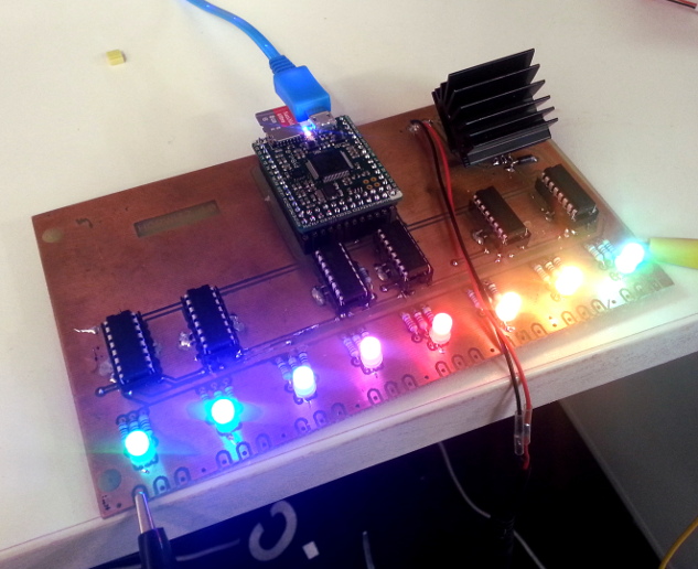
At first I designed the board to be as tight as possible, but this was a complete mess, routes became very long and I had gangs of tracks adding big borders around the board, I found it much better to lay it out a little more spaced. It made the board quite large, it is a bit bigger than a euro card but much cleaner. Using the Press n Peel method I created a double sided mockup of the board, this was actually used in media images of the show! For the connections to the speakers I went for 3.5mm pluggable terminal blocks, these are great.
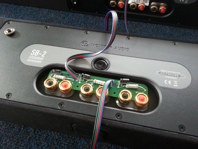
The speaker circuits were directly attached to the back of the speaker, I designed a PCB that could be clamped on the terminals of the speaker, this made it very convenient and made it easy to split the signal to the LED and the speakers. It is very important to limit the amount of wiring in installations as the more wiring the more likely they can snag and break! Enclosing
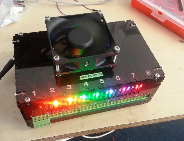
Only issue with using terminal blocks is that they need square holes, for speed I decided to get a box lazercut this also allowed me to put markings on it and cutout a fan for a hole.
 The Enclosure