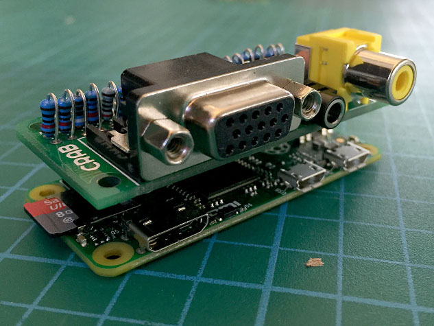
VGA cap
 Here is a PCB I have designed, it was made in response to the release of the Raspberry Pi Zero. For a low cost it helps to break out the analogue outputs from the zero. The analogue ports it provides are stereo audio, composite and VGA. This is all on the same edge as the Zero’s existing connectors. This board is ideal if you want to utilize a computer monitor, especially if it has built in speakers like many ‘multimedia’ TFT screens that now cost very little second hand. Apart from the composite output it will also work on any Raspberry Pi that has the 40 pin GPIO header (Raspberry Pi A/B+ and the Raspberry Pi 2) I am fund raising to make a bunch of them on Kickstarter see here
##It is a kit
To make it as cheap as possible and easy to adapt for different purposes it is a kit / bare PCB that uses only through-hole components. Due to a lack of space all components are folded this may make it a little fiddly to construct if you have less experience but it is not too hard.
What this means though is that you can choose which way up the cap is mounted, if you what the VGA or not and if you are building into an enclosure the pads can be directly soldered.
##Enabling the outputs
Full instructions can be found on crab.design
Due to space and cost the cap does not have auto configuration EEPROM as defined by the HAT specification. It has to be set up by editing the config.txt and adding files to the /boot/ partition.
For VGA it uses Gert van loos VGA666 circuit which uses a passive resistor network to perform the Digital to Analogue conversion. The pins it uses are slightly different to allow for the audio to also be broken out of the GPIO header. To activate VGA an ‘overlay’ has to be added to the configuration files of the boot partition. These will be provided in the Github repository.
Analogue audio is the same as the circuit on the Raspberry Pi B+ schematic, but instead the output comes from the GPIO. To activate another ‘overlay’ is used that comes with the default Rasbian distribution (pwm-2chan-overlay) If this and the VGA is activated only 4 GPIO pins will remain.
The composite is simply an extension of the new breakout pins next to the the Zero’s GPIO header, it is connected by its own socket when the cap is pushed on.
The parts activated are up to the user by simply disabling and enabling parts in the config.txt file. More information will be up soon at the crab github pages.
What is crab?
Crab is going to be a series of circuits that I think are useful repeatable modules for use in installations. That is not strict though, I am also designing circuits and boards that can inspire ideas and teach that may not be so practical.