Analogue Voltmeter kit
EuroClack — CV voltage meter
Part of EuroClack.
Description and specs
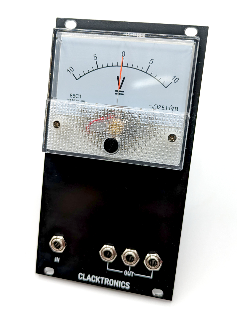
Introducing the Clacktronics Analogue Voltmeter, the perfect addition to your modular setup for those seeking a touch of vintage charm and DC voltage signal monitoring. This partially assembled kit provides you with the necessary driving circuitry and analogue meter, allowing you to seamlessly integrate a classic voltage needle meter into your rack.
The Analogue Meter not only adds a visually striking element to your modular system but also offers practical functionality. With its ability to measure slow signals ranging from +10V to -10V, you can now visualize the behaviour of your slow-evolving CV signals in real time. Whether you're working with complex modulation sources or fine-tuning your patches, the Analogue Meter provides a clear and intuitive way to monitor your signal levels.
As a bonus, the Clacktronics Analogue Meter features three buffered mult outputs, expanding your patching possibilities and ensuring that your signals remain clean and robust throughout your system. These mult outputs allow you to distribute your CV signals to multiple destinations without compromising signal integrity.
The Analogue Meter kit comes partially assembled, striking the perfect balance between convenience and the satisfaction of being involved in the building process. With clear instructions and pre-soldered components, you'll be able to complete the assembly with ease and have your meter up and running in less than an hour.
Width: 14HP
Height: 3U
Depth: 50mm
Current draw +12V: 2mA
Current draw -12V: 2mA
Available to buy from
Thonk (wayback mirror)
Bill of Materials
Part                             Value              Designators     Notes
-------------------------------  -----------------  --------------  --------------------------------
-- On-board connectors --
Power socket                     IDC 2.54mm 10-way  J4              normal Eurorack power
Thonkiconn jack                  PJ398SM            J1, J3, J5, J6
Screw terminal                   5.08mm             Voltmeter       marked 'voltmeter' on panel
-- SMD (pre-soldered in kit) --
MLCC                             100n, 5mm package  J4              X7R, Y5V or similar
Schottky diode                   SMA package        D1, D2          any SMA Schottky
Resistor                         100R               R1, R2, R3      0805 package
LM324                            SO-14 package      U1              chosen because it was cheap!
-- Other bits --
Panel meter                      85C1, +/-10V       On panel        other voltages available
2 wires                          any type           On panel        need solder tags
Solder tags                      hole for M3 bolt   On wire         solder onto the wire
Brass standoff M3                8mm body           On panel        threaded one end, bolt the other
2 extra M3 nuts                  M3 standard        On panel        raise the standoffs (see build)
Assembly Video
Coming soon.
Assembly
The assembly instructions are shown for the complete kit that is for sale. If you source your own components the parts may look different. Sometimes it is hard to convey in text and image the exact details of assembly so some information may be a bit confusing especially if you are starting out. A video is also available that may be more helpful to follow along.
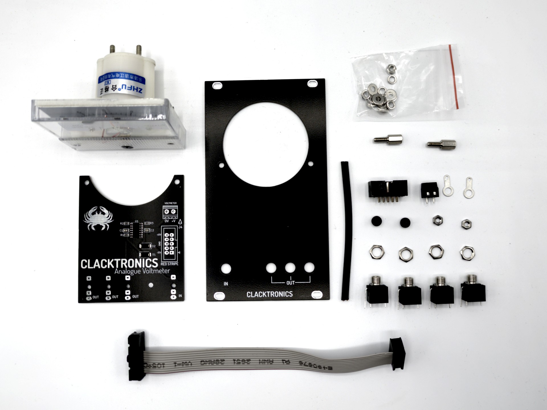
Components in bag
You should have the following small components in an anti-static bag. Some parts in the baggie of screws are not used because they come with the meter as a product.
The PCB
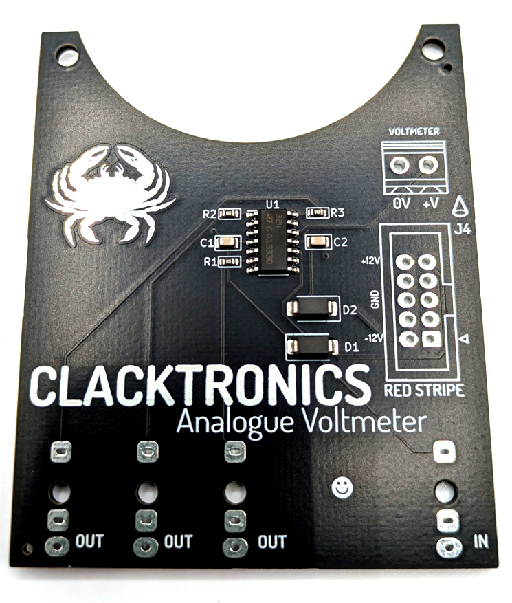
The PCB is pre-assembled with surface-mount components — it made it cheaper to produce. All you need to do is solder the IDC connector and screw connector on the top and the jacks on the bottom. Take care not to solder the jacks on the top side!
Top connectors
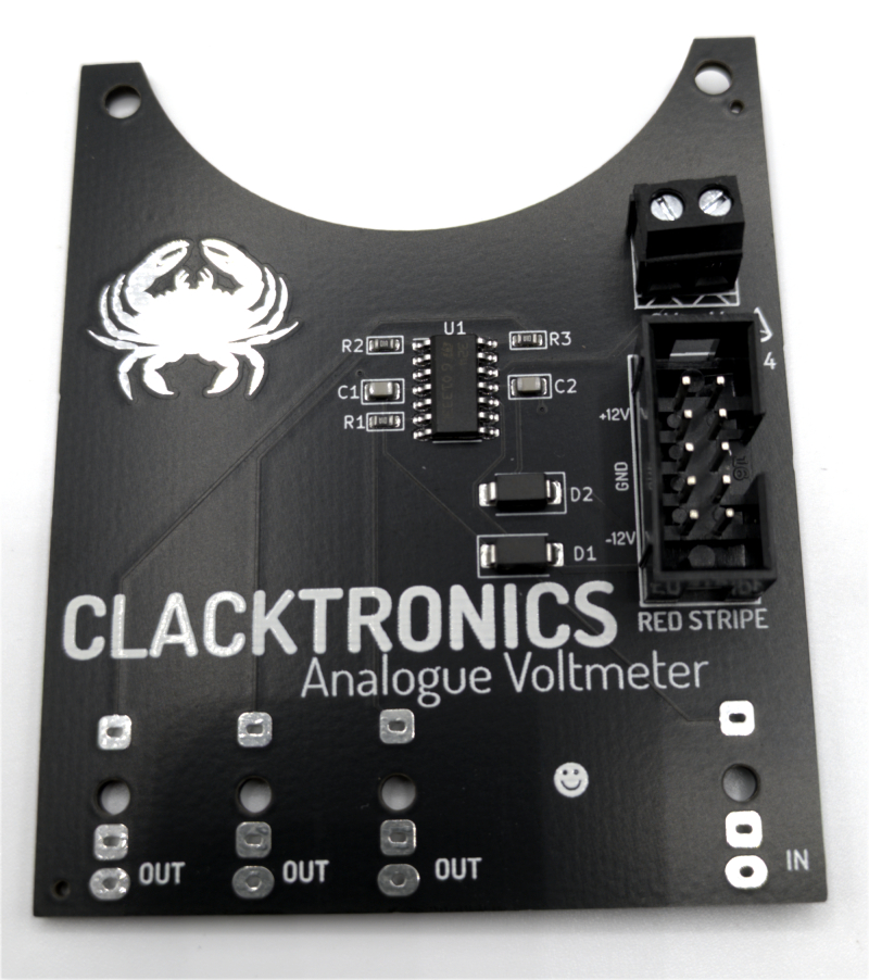
Solder on the connectors; they should be on the side with the crab symbol. Take care to notice the orientation of the IDC connector (the 10-pin one): there is an arrow on the connector that matches the arrow on the board, plus there is a notch in the connector that matches the notch marking on the board. Take care to make sure the screw terminal is soldered so the holes face outwards.
The jacks
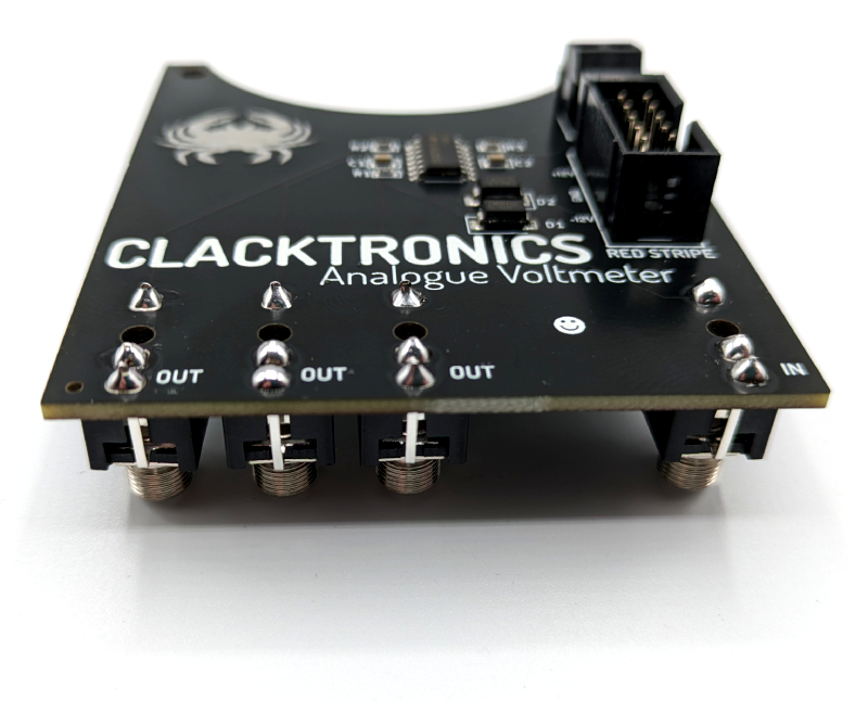
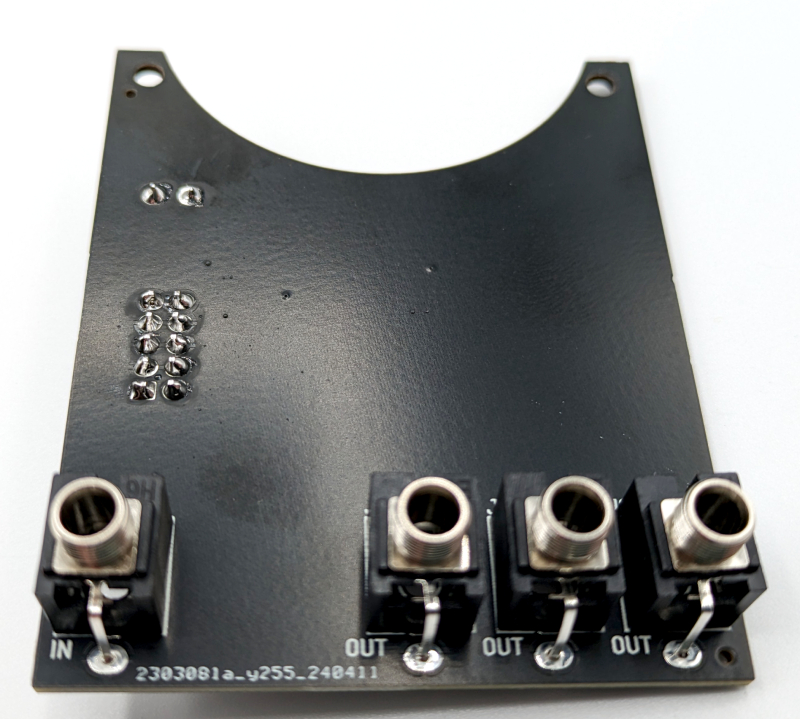
Solder the jacks on the underside — it's the side without the crab symbol on it. That is it! The main board is assembled.
Panel and panel-meter assembly
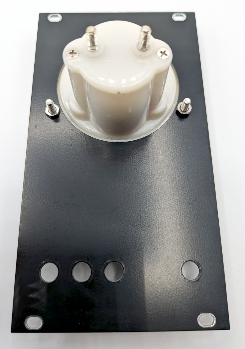
Fit the meter into the panel; it should go in easily. Use two M3 nuts to screw it into the panel as pictured.
All the mounting parts
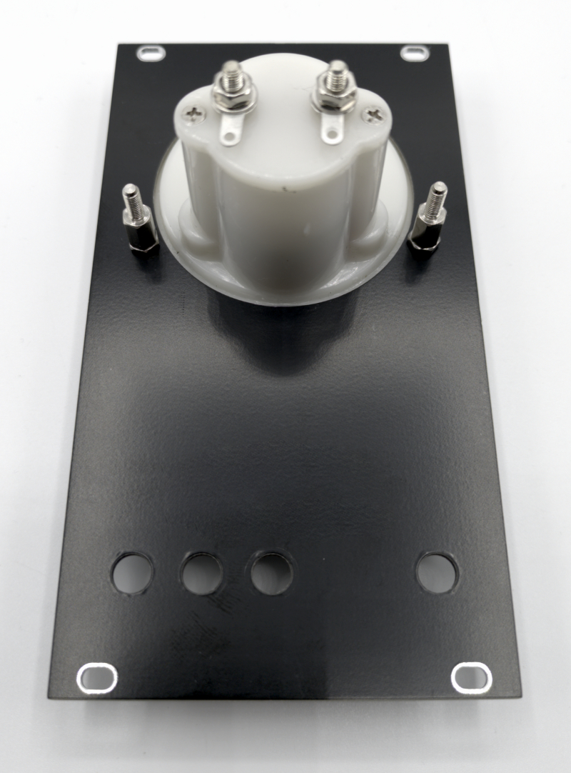
Next, screw the PCB spacers on top of the M3 nuts we just placed; this ensures the correct height for the PCB mounting. Then also put on the solder tags. I like to do "washer > solder tag > washer > nut" but there are also anti-slip washers in the package too if you want to use them.
Mount the main PCB
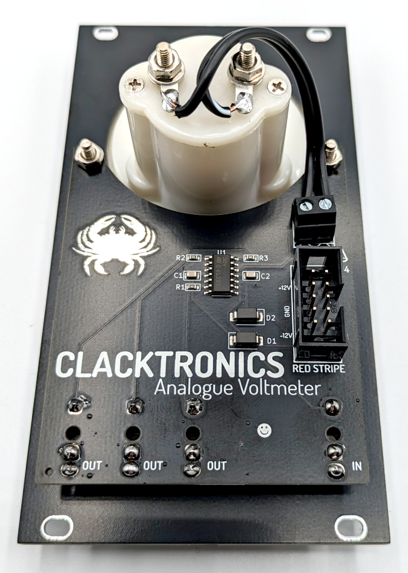
The PCB should sit on top of the meter now, as pictured. Use the jack nuts to secure it in place and then a further two M3 nuts to hold it into the meter. Now you are done — the meter is complete!
Downloads and Resources
Troubleshooting
When I put in a positive voltage the meter moves to the left and vice versa
You need to swap around the wires on the meter, either at the terminal or on the back of the meter itself.
I soldered a connector on the wrong side or the wrong way around
Oh dear! We have all done this. Use a good quality solder pump like an Engineer SS-02 to remove as much of the bulk solder as you can. Then use wick to remove as much trace solder as you can (Gootwick is a good brand), paying attention to both sides. Then use a small screwdriver to "click" the leads away from the edge of the hole and the part should ease out. Finally, use more wick to clean up the hole and resolder.