Mini-Speaker kit
EuroClack — audio monitor module
Part of EuroClack.
Description and specs
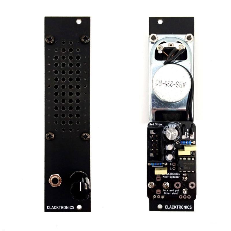
This project is a simple audio monitor module for your Eurorack. It consists of a speaker driver mounted onto an FR4 panel with an amplifier board. Much like the EDP Wasp or the Arp 2600, it will not be the most high definition speaker, especially lacking at the low end, but it is handy for when you may not be able to access your monitors or if you are using a small portable system.
As a kit it is designed to be simple and fast to assemble, so ideal for beginners. There are only a handful of components to solder so it should give fast gratification and troubleshooting should be simple. The speaker is exactly 30.5mm wide which means it just fits into the 6HP (30mm) panel width.
Width: 6HP
Height: 3U
Depth: 50mm
Current draw idle: 5mA (+12V), 0mA (-12V), 0mA (5V)
Current draw active: 80mA (+12V), 0mA (-12V), 0mA (5V) when driven with 10Vpp square wave at 500kHz
Available to buy from
Pushermann (wayback mirror)
Thonk (wayback mirror)
Bill of Materials
Part                     Value                         Designators  Notes
-----------------------  ----------------------------  -----------  ---------------------------
Capacitor, unpolarized   100nF                         C1, C3, C5   pin pitch 5mm
Capacitor, electrolytic  1000uF                        C4           10mm dia, pin pitch 5mm
Capacitor, electrolytic  10uF                          C2, C7       5mm dia, pin pitch 2mm
Resistor                 470K                          R1           1/4W
Resistor                 10R                           R2           1/4W
LM386N-4                 LM386N-4/NOPB                 U1           Must be -4 version (1W out)
Potentiometer            10K linear                    RV1          RK09K, centre detent
Power socket             Shrouded 2.54mm 10-pin (2x5)  J2
Thonkiconn jack          PJ398SM                       J1
Assembly Video
Assembly
The assembly instructions are shown for the complete kit that is for sale. If you source your own components the parts may look different. Sometimes it is hard to convey in text and image the exact details of assembly so some information may be a bit confusing especially if you are starting out. A video is also available that may be more helpful to follow along.
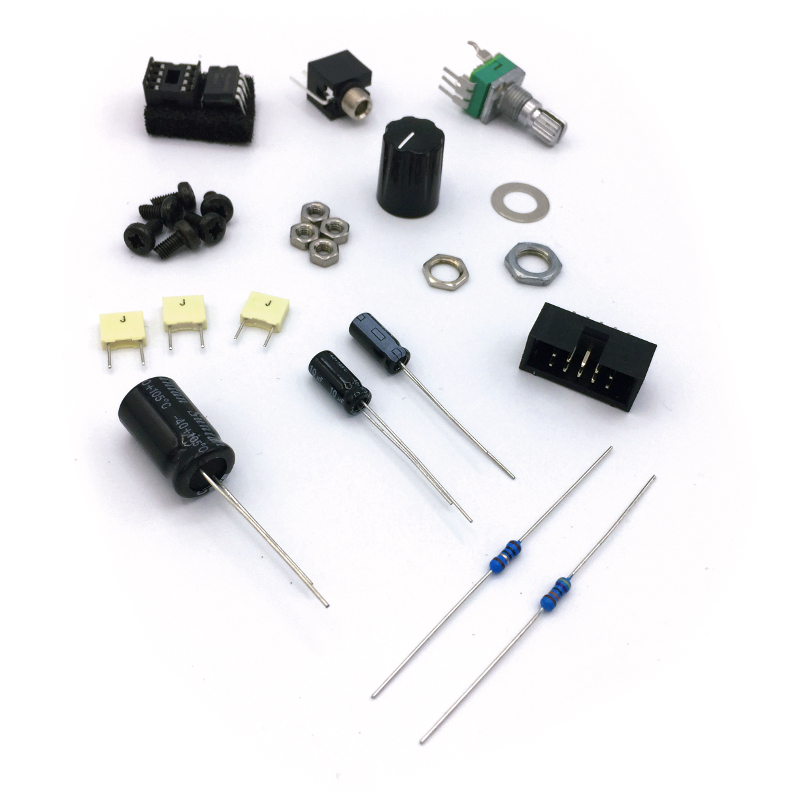
Components in bag
You should have the following small components in an anti-static bag.
Other parts
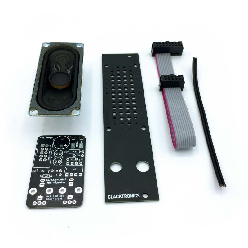
There should also be a speaker, a panel, a PCB, a wire and a 16-to-10 pin power cable.
The PCB
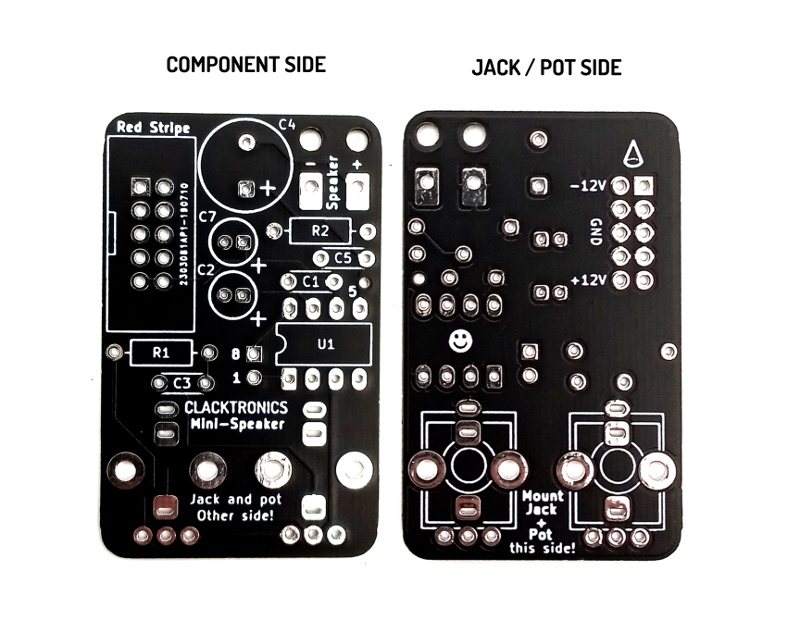
All components are fitted on the top of the PCB apart from the audio jack and the potentiometer. Make extra sure you are fitting the component into the correct side, as it can be hard to remove once soldered!
Resistors
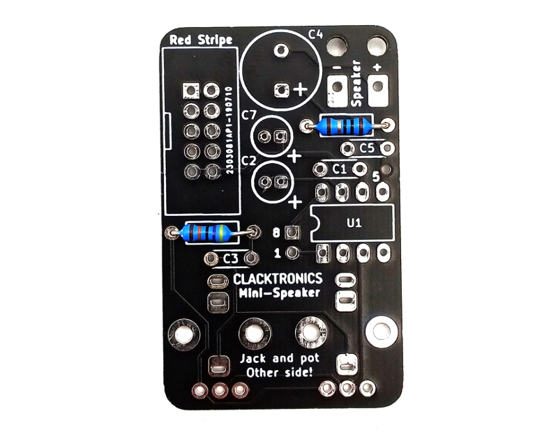
Fit the two resistors. R1 is 470K and R2 is 10 Ohms, the markings are as follows:
470KΩ = yellow, purple, black, orange
10Ω = brown, black, black, gold
Strip the wire
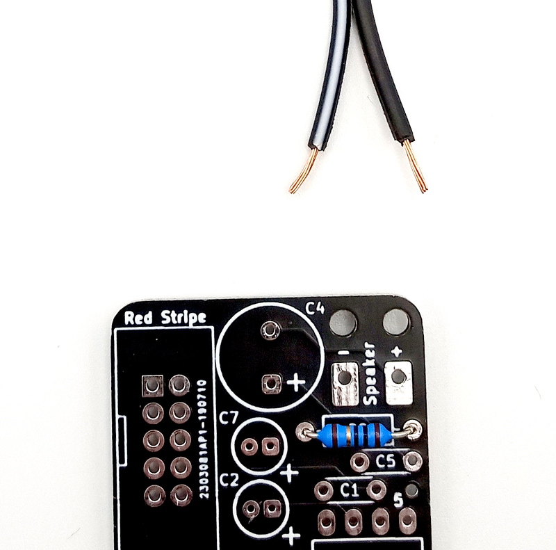
It is best next to add the wire for the speaker. This is because it can be hard to do once the larger capacitor is in place. Split one end of the wire and strip about 5mm of the end.
Feed the wire
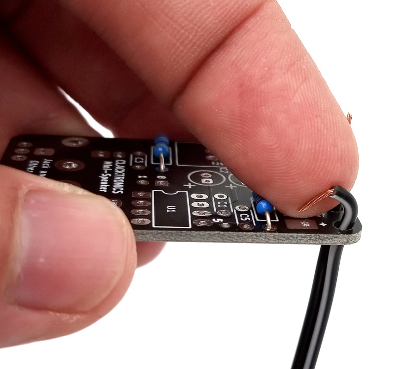
The wire is restrained by feeding it through two holes and then into the solder pad. Whilst it is not totally necessary it can make it a bit more rugged. The markings on the wire can go any way around; I like to use white stripe for + and no-stripe for -.
Fix the wire
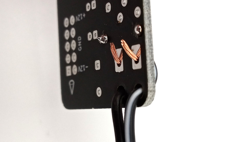
Feed the wire through the hole and bend it over so it holds in place so you can solder.
Wire in place
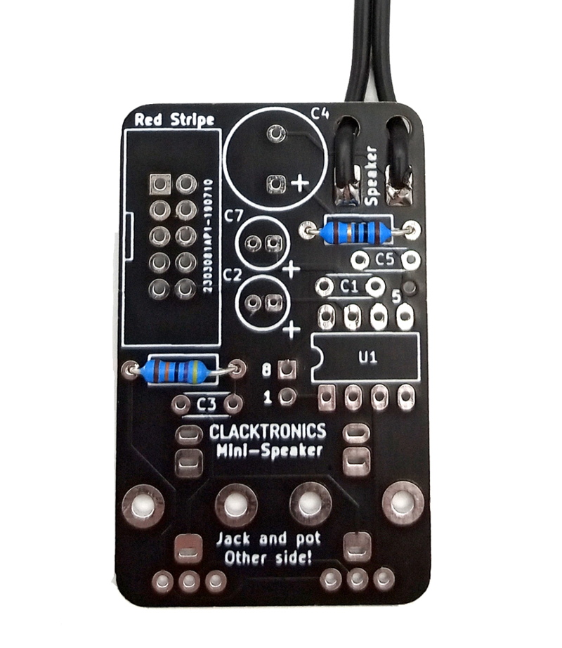
The wire should now be in place and look like this.
Film capacitors
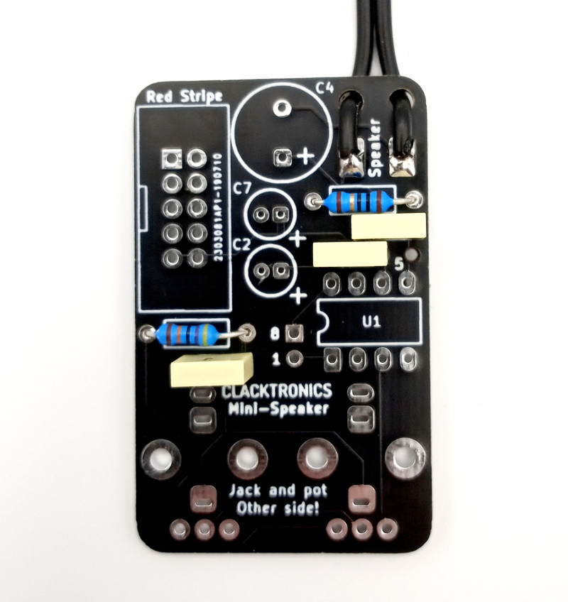
The kit includes three yellow box capacitors. They are not polarized, so they can be fitted any way around. They are all the same value and fit in C1, C3 and C5.
Smaller electrolytics
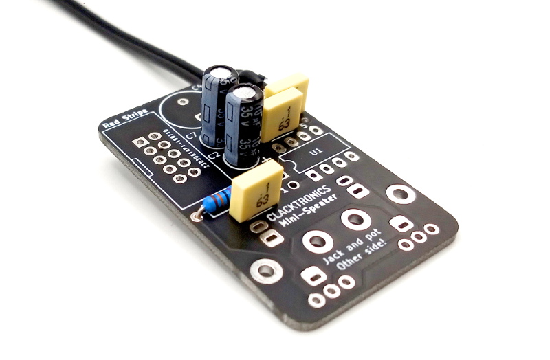
You can now fit the smaller 5mm electrolytic capacitors. They are polarized and are marked on the negative lead with a minus symbol. The PCB has a + symbol for the positive side; place them in as shown.
The big electrolytic
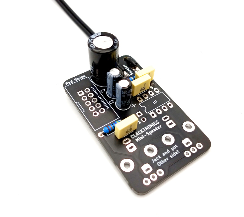
This capacitor makes sure no DC goes to the speaker. It is also a polarized electrolytic capacitor, fit as shown. The markings are the same: the negative is marked on the capacitor and the positive is shown on the PCB.
Fit the socket
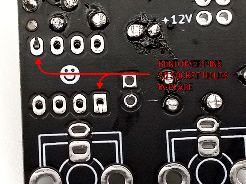
To make it easier and to prevent damage to the IC a socket is used. This is the 8-pin socket pushed onto the black foam. This socket is also polarized: there is a notch at the top to show its orientation and the PCB has a marking to show this. You could use blu-tack to hold the PCB down and fit the socket, but a trick I like to use is to hold the socket in and bend the pins.
Make sure it is fixed
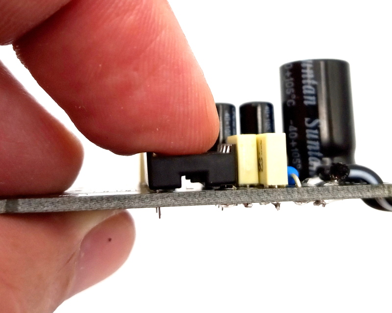
Before properly soldering, make sure the socket is sitting flush on the PCB.
Fit the power connector
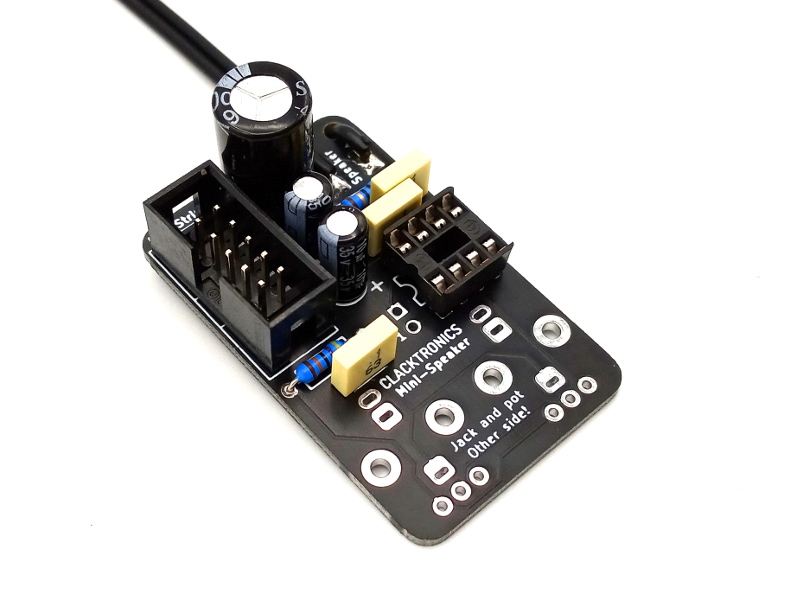
This is the power connector. It is hard to show in photos; a trick to get this in place is to tack one pin with solder whilst holding it in place with your hand. This is shown in the assembly video on this page.
Fit the jack and the potentiometer
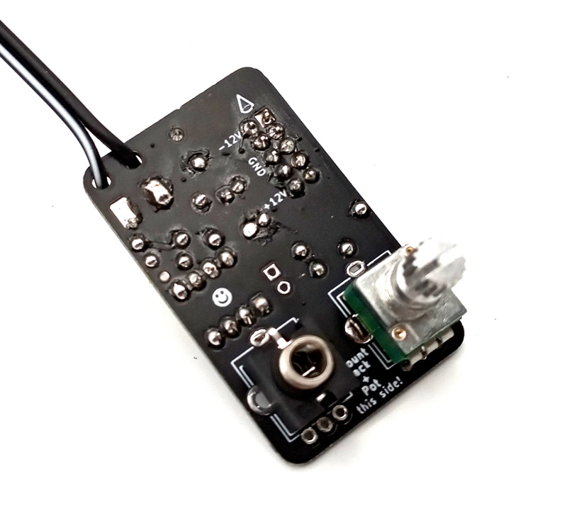
Be very careful here — a misplacement will cause a lot of headaches. Make sure you know what orientation you want the module to be in. This can be either audio-in left and pot right or vice versa. Also, these components are placed on the other side of the board; push the parts in and test them out with the panel to make 100% sure it is correct.
From the side
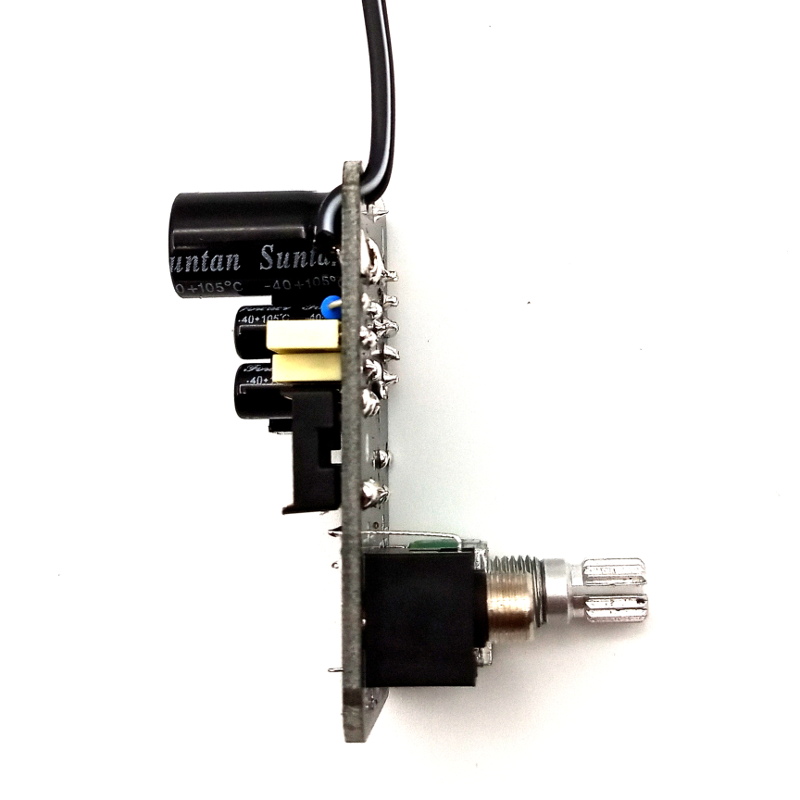
This shows how they should be fitted.
Main assembly
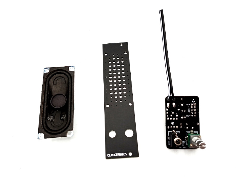
You should now have these three parts.
Mount the speaker
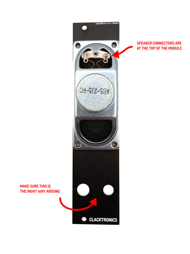
There are four black bolts and four silver M3 nuts in the kit that hold the speaker in place. The speaker has to be mounted with its solder tabs upwards. Before screwing in, make sure you have the front panel the right way.
Fitting the board
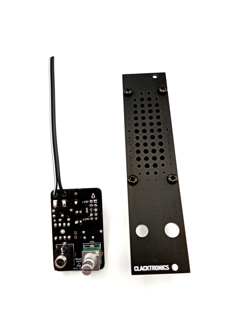
Now it is time to fit the board to the panel. Put the potentiometer and the jack that is attached to the main PCB into the panel. There is a hex nut provided for the jack and a washer with hex nut for the potentiometer.
Trim the speaker wire
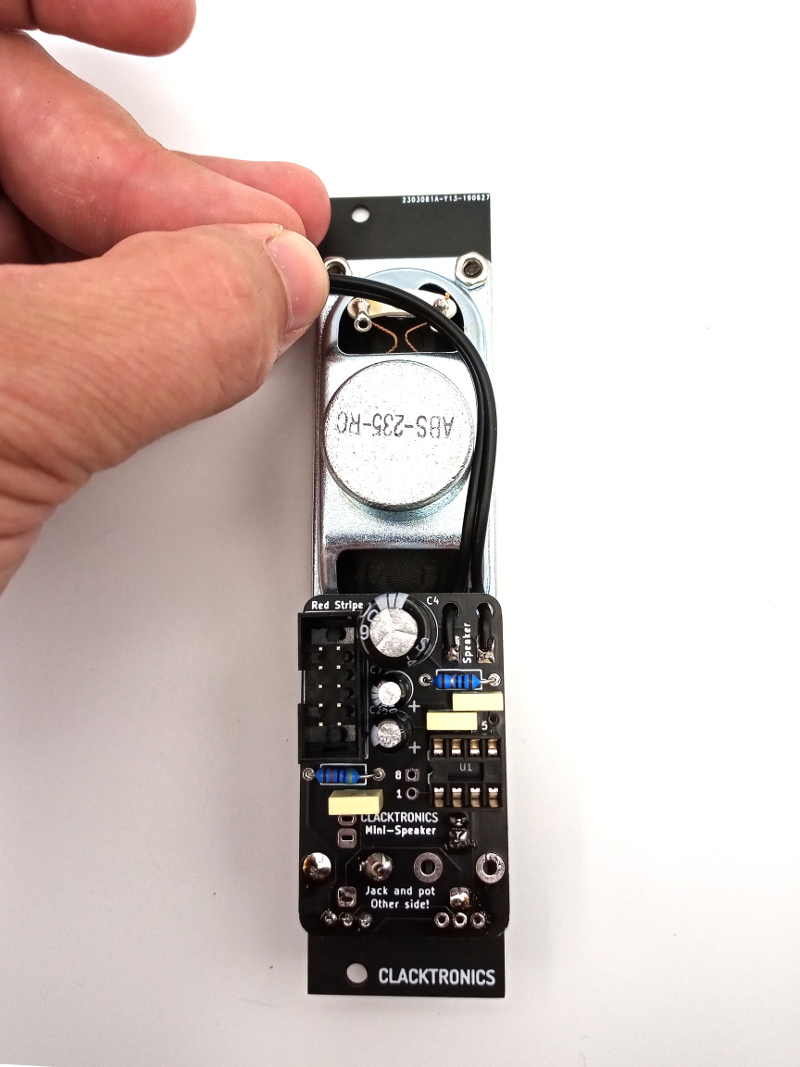
Once fixed in, trim the wire to the correct distance to the solder tabs of the speaker and strip the ends 5mm. Solder + to stripe and - to no-stripe on the speaker terminals.
Finished!
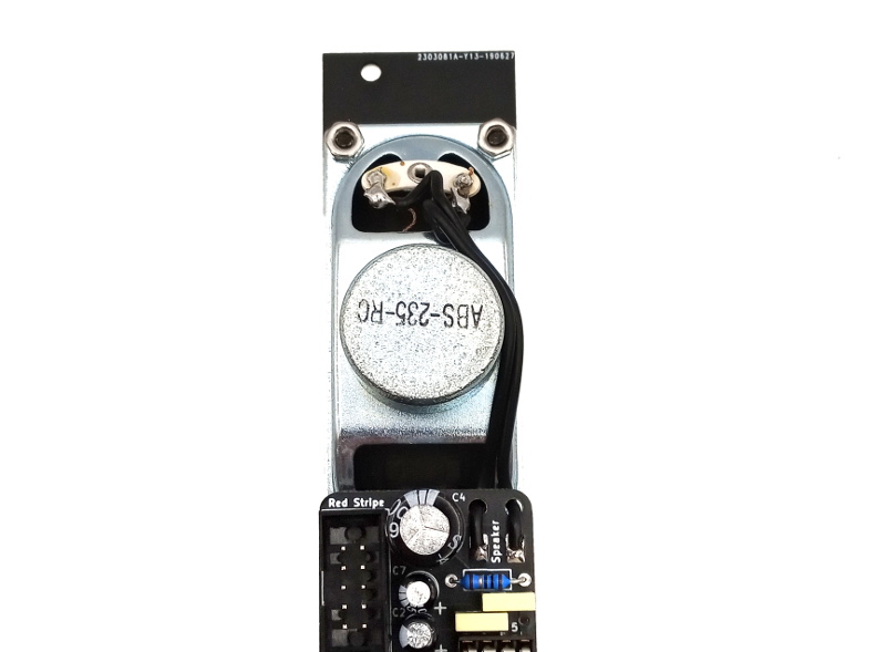
It is built!
Smoke test
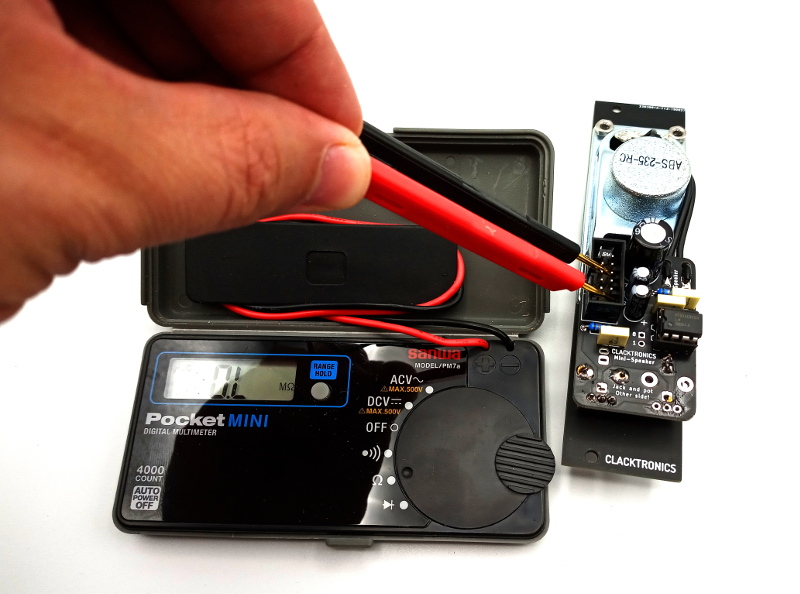
Before plugging into your system, it is recommended to power it from an isolated power supply, ideally with current limiting. A basic test you should do is to use a multimeter in resistance mode and check the resistance across +12V and GND — this can be found on the connector as shown. Any reading below 1K is suspect. This is not foolproof; visually checking your board and all the components in place is essential.
Downloads and Resources
iBOM (right click to save)
Schematic (right click to save)
JPEG front view (1.2MB)
Troubleshooting
No sound or quiet
Make sure you have soldered all the pins of the potentiometer.
Check R1 and C3 are correct.
Check there are no bent pins on the IC going into the socket.
Check C4 is the correct way around.
Humming, loud and clipping
Have you swapped R1 and R2?
Notes and Errata
All is good — there have been no circuit changes since its release.
Colour changes: polyester capacitors are now grey, 10µ electrolytics are gold stripe.
Change the value of R1 down to get more gain. Note the IC will get hot; heatsink it to improve performance at higher gain.