Proto-PSU kit
EuroClack — prototyping power supply
Part of EuroClack.
Description and specs
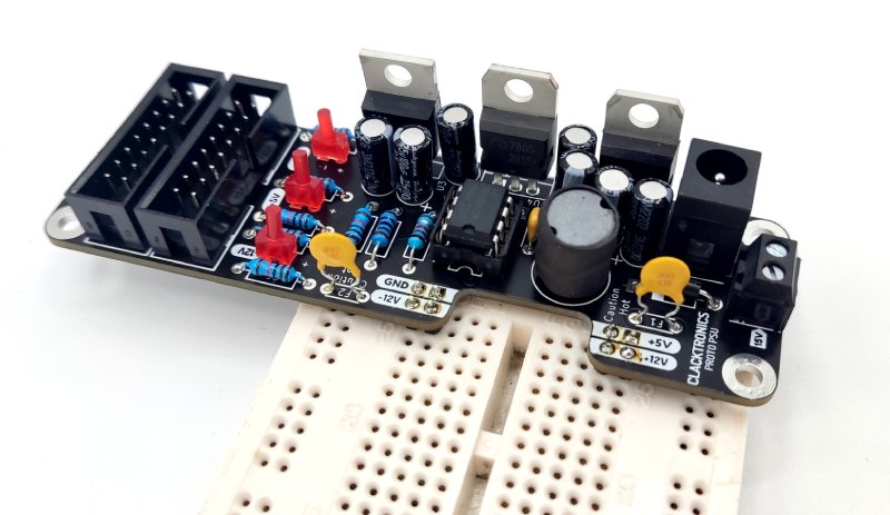
Proto-PSU is an easy-to-assemble DIY kit that is designed to make it easier and cheaper to have a dual-rail power supply, typical of DIY synths, for prototyping purposes. Its 4-layer PCB design uses through-hole components that are clear and easy to solder. It is versatile: it can be a breadboard-attached supply, an internal case supply or a module-style power supply depending on how you configure it. There is no need for a specialist AC supply or to use mains electricity — it runs off a 15VDC adaptor. It comes with two resistors for R1 so you can either keep the PSU cool at a limited 80mA for -12V or drive it a little harder, keeping an eye on how hot it gets. I recommend keeping to 1Ω for R1 and then replacing it with the smaller resistor if you need more.
Take care!
This module uses no dangerous parts, but if not built properly or is over-driven even very slightly it will get very hot and burn your fingers. Make sure the core components are all properly installed in the right place and polarities are correct. The polyfuses are for protecting against shorts but not for over-currents; if, for example, the -12V rail is driven over 100mA but below 500mA, the MC34063 will get very hot and so will the 7912 regulator.
Width: 6HP
Height: 3U
Depth: 50mm
12V and 5V shared current: 300mA
-12V: 80mA
100mV ripple
Available to buy from
Thonk (coming soon)
Caveats and warnings
It is not only called "proto" because it is for prototyping but also because it is just a test PSU you use before you attach your design to a bigger, nicer one. There are a few limitations that you need to be aware of just so it meets your expectations.
Current is limited to 80mA for -12V (if using 1Ω for R1) and 300mA for both 5/12V. The polyfuses will blow if this is greatly exceeded (a short) — don't worry, they will reset.
If you use the 0.22Ω resistor, be cautious that there is a gap between the MCP34063 and LM7912 getting really hot and the polyfuse actually blowing. This is why the 1Ω is recommended.
The switching supply IC MCP34063 is supposedly an 80s design; that's how it was possible to get a DIP-8 part — it is probably the closest to a jellybean DC converter you can get. It switches at approximately 100kHz which will be audible at higher loads near 100mA of the -12V rail. You must follow some good design practices (that you should be doing anyway!) such as not directly connecting voltage references to the rail — for example with op-amps when you need an offset voltage or pot reference. Or you might not give a damn as you are hacking away!
The nature of polyfuses means that if you only slightly exceed the 300mA current the fuse might not open completely; it could cause the voltage to droop but not go low. This may cause frustration if you are unaware — keep measuring rails. Also, if using the 1Ω resistor, the -12V rail will just drop (rise, as it is negative!) in volts the more you go above 80mA. This keeps the device very cool but could also confuse you if you are looking at a design.
When using it in Eurorack module configuration, take care to notice that the tab of the regulators is bare and may touch something.
Another issue with the polyfuses is they have a resistance; any circuit that pulls power in pulses will make the line noisy. If this is an issue, either short them or remedy with a capacitor.
Bill of Materials
Part                     Value                       Designators             Notes
-----------------------  --------------------------  ----------------------  -----------------------------
Capacitor, electrolytic  100uF                       C1, C3, C4, C5          pin pitch 2mm
Capacitor, electrolytic  10uF                        C6, C7, C9              pin pitch 2mm
Capacitor, ceramic       220pF                       C2                      pin pitch 5mm, NPO/C0G
Schottky diode           1N5819                      D1, D2                  DO-41 footprint
Red LED (2mm)            2mm package                 D3, D4, D5              front or back placement
Polyfuse 300mA           JK60-030                    F1, F2                  3mm LED footprint
Power inductor           220uH                       L1                      pin pitch 5mm
Resistor                 1R (80mA) or 0.22R (300mA)  R1                      1/4W, sub-1 ohm
Resistor                 11K                         R2, R4, R5, R6, R7, R8  1/4W
Resistor                 1K                          R3                      1/4W
Inverter IC              MCP34063                    U1                      inverting switch supply
Regulator                LM7812                      U2                      +12V linear regulator
Regulator                LM7912                      U3                      -12V linear regulator
Regulator                LM7805                      U4                      +5V linear regulator
DC barrel socket         2.1mm                       J1                      front or back placement
Eurorack power           2x8 IDC socket              J2, J3                  take care with orientation
Screw terminal           2-pin                       J5                      pitch 5mm
Breadboard header        2x2 pin header              J6, J7                  place in breadboard to solder
Pillars                  M3 x 12mm                   4 pcs                   panel version only
Black screws             M3 x 6mm                    10 pcs                  pillars and rack mounting
PCBs                     Black 1.6mm                 2 pcs                   main PCB and panel (optional)
Assembly Video
Assembly
The assembly instructions are shown for the complete kit that is for sale. If you source your own components the parts may look different. Sometimes it is hard to convey in text and image the exact details of assembly so some information may be a bit confusing especially if you are starting out. A video is also available that may be more helpful to follow along.
Components in bag
You should have the following components.
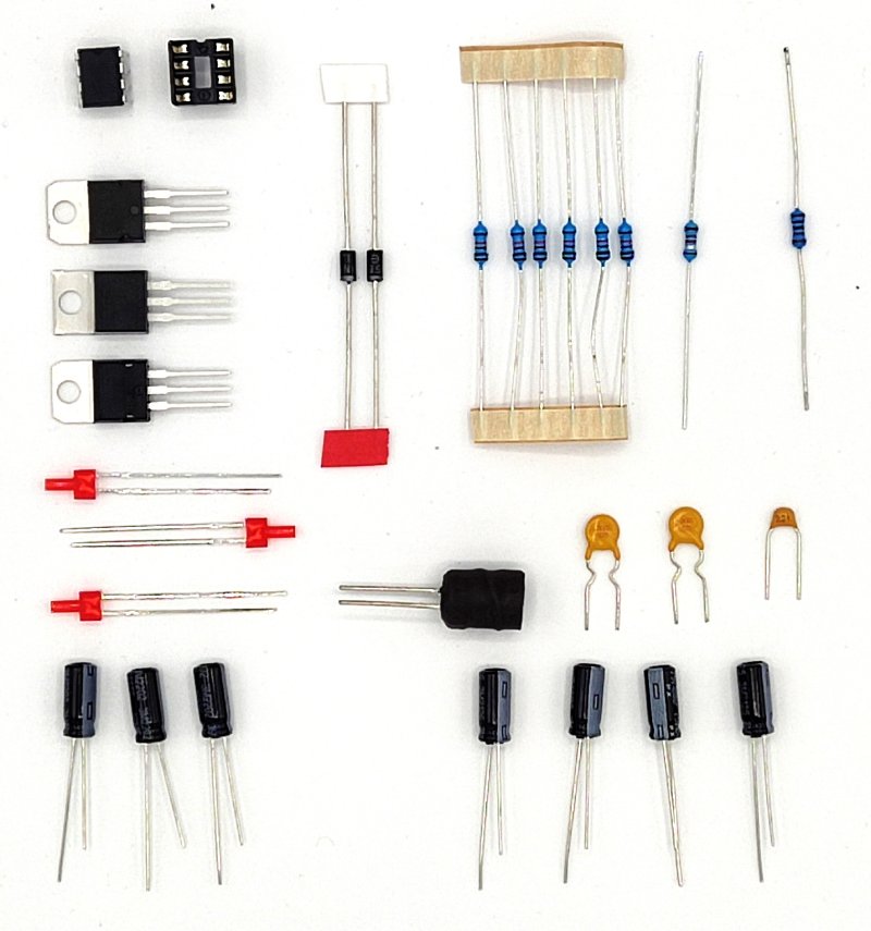
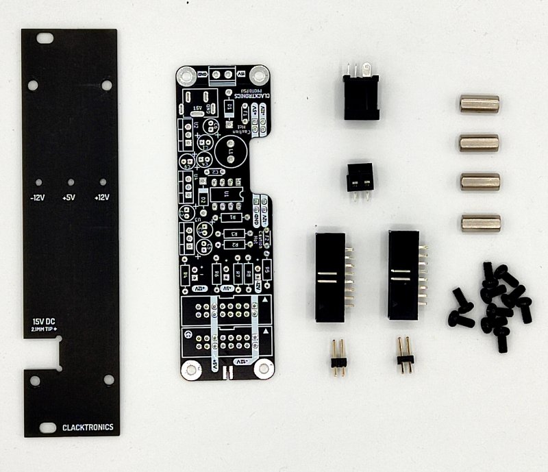
Hardware
All the hardware, PCB and panel.
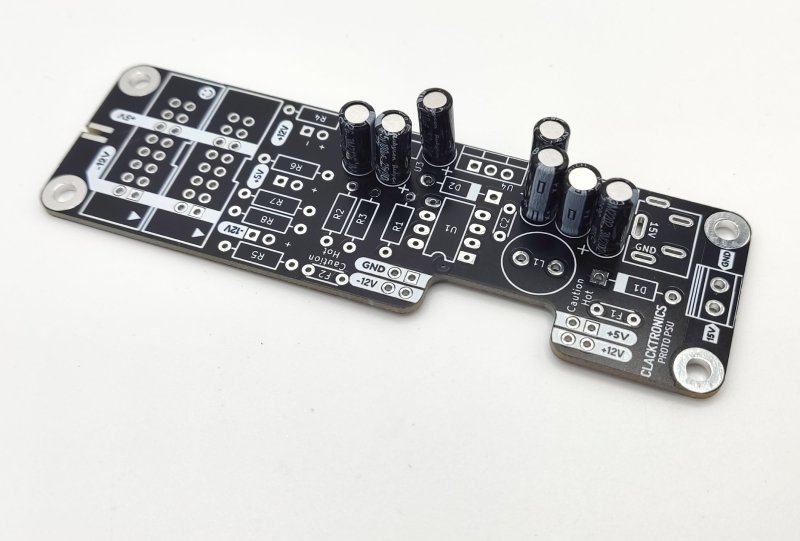
01 — Mount capacitors
Make sure you get them the right way around. Also note there is 100uF and 10uF — get them in the right place.
02 — Mount resistors
Next resistors. Note the colour values; if you are unsure, use a multimeter to check the values.
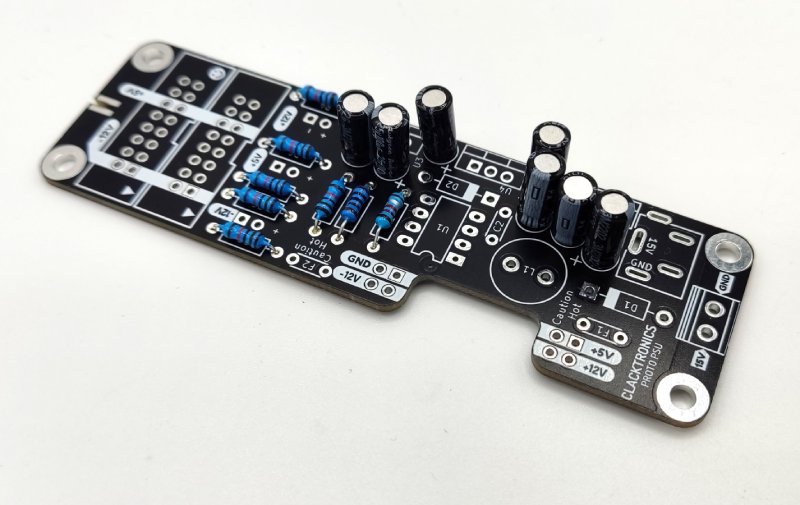
03 — Diodes and fuses
Diodes are polarised — stripe goes to stripe on the PCB. Fuses are not polarised and can go either way around.
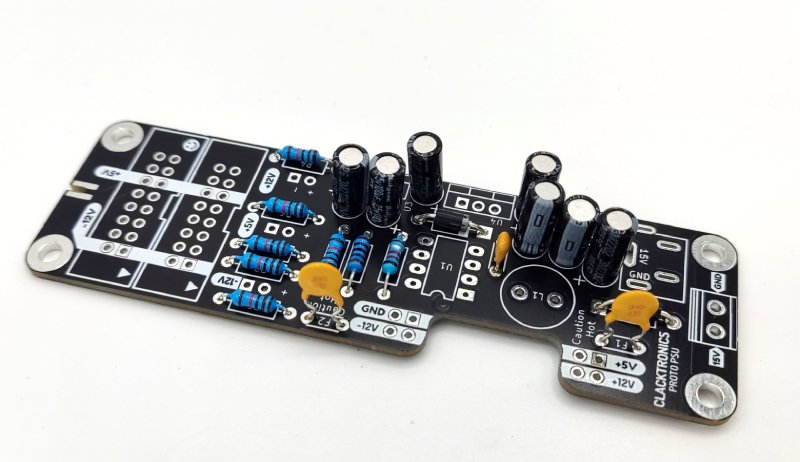
04 — Inductor and regulators
There are three regulators — make sure you put the right ones in the right places: 7812, 7912 and 7805.
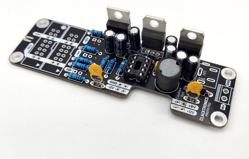
05 — Connectors and terminal
Hold the connectors in with a ball of blu-tack or your hand and tack it in place with a blob of solder on your iron to make sure it is all in place before committing to soldering all the pins.
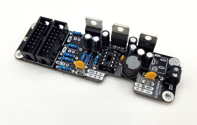
Wait, stop! The assembly now diverges depending on how you want it built
Go to 06A to build the breadboard version, or 06B to complete it as a panel version.
06A — Fit socket and LED
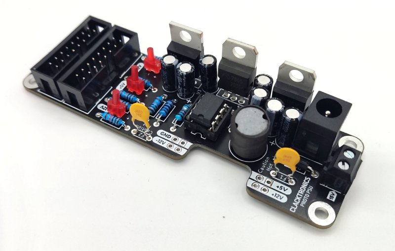
07A — Breadboard version finished!
06B — Add spacers
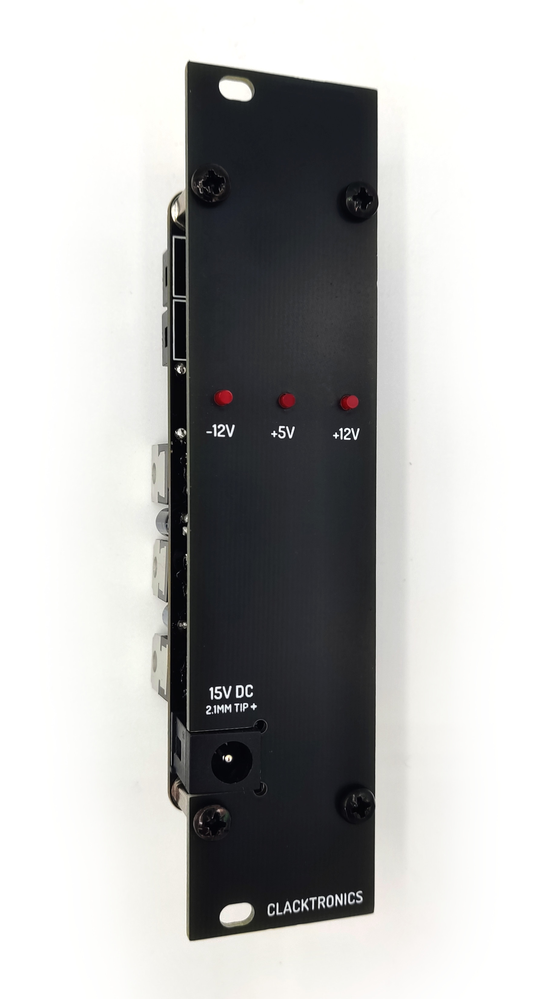
Screw in the spacers to the PCB. We want to attach the panel first, so the panel-dependent components will fit nicely. Solder in the LED at the height you like — I like them sticking out, but you could do them flush.
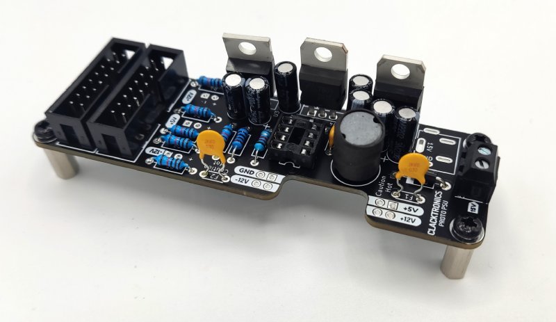
07B — Put on the panel and fit DC and LED
Put the panel on with the LEDs and align it all so that it will look nice.
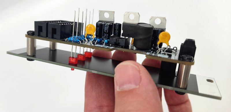
08B — Double check alignment before soldering
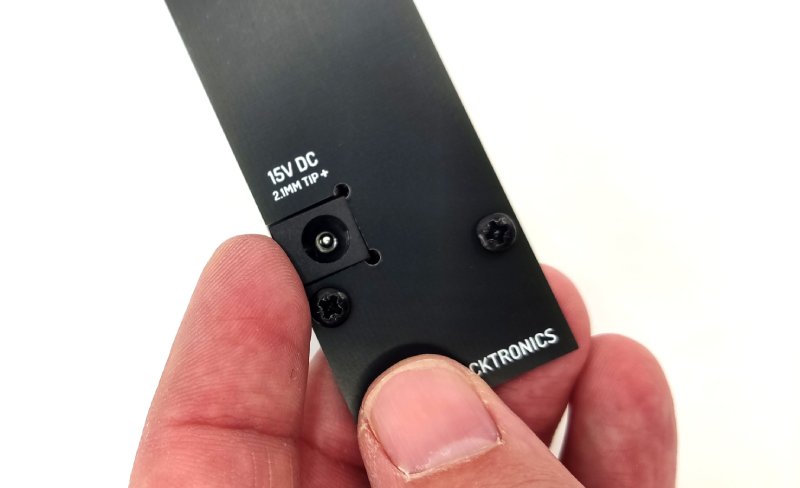
09B — Finished!
Downloads and Resources
iBOM (right click to save)
Schematic (right click to save)
JPEG front view (796KB)