Blog
Posts 6–10 of 47
Page 2 of 10
Boldport Club
02 January 2019 · Open this post on its own
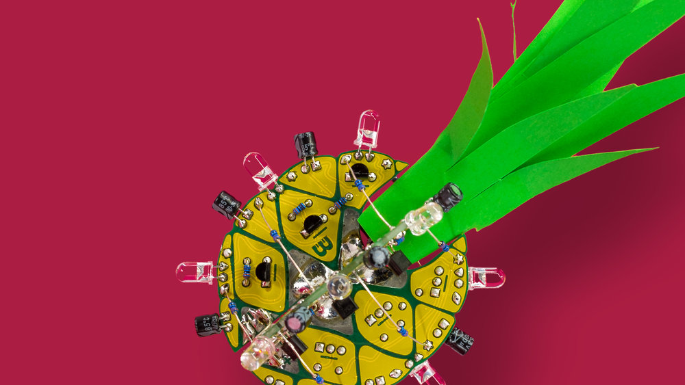
In 2017 I started working for Boldport a PCB design company that specialises in attractive circuit boards and runs boldport club a monthly subscription where you receive a highly designed electronic kit every month. Above is the very first kit I designed called Ananas it was a challenge to make my first design 3D but it turned out very well! Boldport decided to Change the way it works so I decided to write up how the design process works for a project kit. Please read this blog post to find out about how this unique design was made image courtesy Boldport ltd
Paris Opera
26 June 2017 · Open this post on its own

I had the rare opportunity to be a part of a project at the Palais Garnier, that is one of the main Opera house’s in Paris. I was working with Haroon Mirza to produce a live light and projection installation that interacted with a composition by Pierre Boulez called “Anthèmes II” and was a collaboration with the choreographer Wayne McGregor.
“Anthèmes II” was a fairly early production created at IRCAM by Boulez, using the latest technological research at that time. In fact it actually used early versions of “Max” the visual programming software. I had the opportunity to look at the technical document for that work, it was fascinating to see how the work has been adapted for each new advance in technology. Originally using a number of NeXT machines serial linked and processed with FX processors to now simply running on a single Macbook Pro! There are a lot of technical details in the work that I will skim over, but its basically a program that follows a solo violinist reacting and performing with them according to a score. It does things like passing the violinist sound through various FX and panning the results around 6 speakers, also triggering various samplers. The technicians from IRCAM kindly let us receive data feeds from the MAX/MSP program via open sound control so the elements we control could respond to the live sound. Below is an example of the peice played at the BBC Proms.
The Palais Garnier is a very lavish building, with a complicated baroque style gilt interior. Haroon wanted to work with the internal structure of the auditorium, highlighting parts with lights. We focused on the windows that go around the dome of the auditorium, there were 64 little windows on the edge of the Chagall painting, this is an idea number when working computers! Those were each fitted with PARLED’s. The other element of the work was a projected backdrop on the stage, the idea was to make it look a little bit like an oscilloscope. The data provided to move the beam was quite slow so the movement of the dot was simply a rotating dot. I have recently been learning more about using mathematics to produce graphics from the great youtube series called coding with math by Keith Peters. To produce a rotation all I needed to do was use sine and cosine! The software I used to produce the visualisation was Processing.
Haroon typically produces light / audio works by programming Arduino’s (well AVR’s) built in PWM peripheral. To keep the sound but control the DMX lights I simply established a simple serial link over USB to the control program.
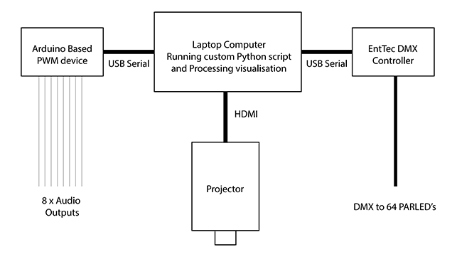
Overall this was a very good experience, I got to try out experimental technology in a fairly low tech live production environment. There is little public recordings of the performance but bellow is a small excerpt from the rehearsals showing the projection and the lights performing.
Cryptocoin ticker
20 June 2017 · Open this post on its own
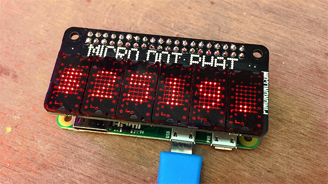
A Quick 5 minute build and possibly a prototype for a future project. I took the Pimoroni micro dot display, which is suitably retro looking, like an 80s/90s stock exchange. Although it is LED, it actually looks a bit like an old Vacuum fluorescent display! The code is a very simple Python script that uses Coinmarketcap API (I chose them because they pull all the coins together) which is simply just provided as JSON, the API allows you to request by currency so I just pulled the ones I wanted and fed the details into a single string that loops on the display.
See the python code below, it gets the details of the coins one by one and pulls the dollar value of them, concatenating it into a single string that is fed into the Pimoroni module for loading up text on the display. It only requests new information every 20 loops to lower demand on the API as it is probably request limited.
from time import sleep
from microdotphat import write_string, scroll, clear, show
import json
import urllib2

# choose currencies to display
currencies = ['bitcoin', 'litecoin', 'dogecoin']

while True:
    ticker = ''

    for currency in currencies:

        url = "https://api.coinmarketcap.com/v1/ticker/%s/" % currency
        data = json.load(urllib2.urlopen(url))[0]

        ticker += '%s ' % data['symbol']
        ticker += '$%s ' % data['price_usd']

    for i in range(20):
        clear()
        write_string(ticker, kerning=False)
        for c in ticker:
            show()
            scroll(amount_x=8)
            sleep(.5)

    sleep(10)
Here is a Demo of it working, it can simply be run at startup ensuring there is an internet connection.
Scanner Cloud
18 May 2016 · Open this post on its own
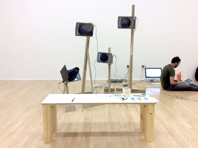
Yes its true, I now do more than synths so my posts have diversified a bit although some new synth stuff coming soon, watch this space! This is a project I did a few months ago for Foxall Studio concept was to get around 50 flatbed scanners scattered around an exhibition space scanning in unison. Then creating clustered mosaics of images from the results that were displayed in the space using projections and printers. My task on the project became how to connect and power all of these scanners. We ended up using Raspberry Pis because it offered us the low cost and flexibility to position the scanners anywhere. I was sent this image below when the scanners arrived!
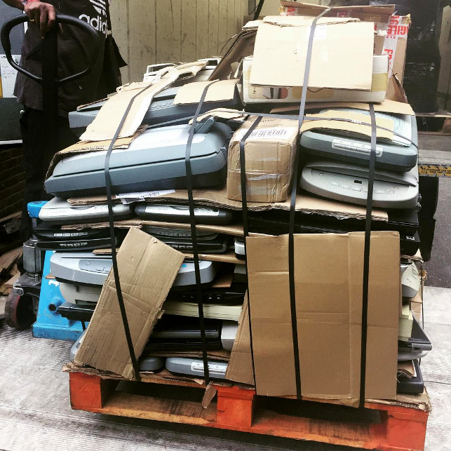
That is a lot of testing to do! they were all second hand from a recycling center I believe.
On top of the function of scanning, the images from these scanners had to be shown in the space on a projector, be printed and hosted on a website.
So the challenge was
How control configure all the scanners easily and at once
How an application can pull these images from the scanners without having to try any special protocols or drivers.
If you had to iterate over 50 flatbed scanners every time a configuration needed changing that was a problem. There were many many different ways I explored how this could be set up, but the solution I ended up choosing was the one that was the quickest to prototype and made compatibility easy. In Linux compatibility was provided by the amazing SANE driver and pyinsane bindings for it in python so I could control the scanner. Then I turned each scanner into a basic web server using Python's BaseHttpServer which I love because it is the most simple and easy to use module. On each GET request the server would scan and return an image. Parameters such as resolution or colour mode could be simply put in the URL such as "http://scannerurl/?mode=color&resolution=100". My program also pulled info from the scanner and presented in under the root URL port 80. Why did I not use a lower level protocol to send images? I figured that there is not one contemporary programming language that does not have a quick library for HTTP requests, plus you can test it in browser!
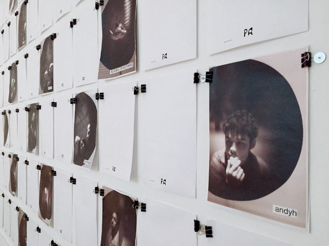
Some of the cameras had lenses attached to them that is why the images look like photographs this idea by Foxall Studio was to bring back the age of having to sit and wait for the photo to take like the dawn of photography. Where if you did not sit still the image distorted!
I then worked with Sebastien Dehesdin who produced a node.js server that pulled all the images from the scanners and served them online. Both of us could not install the work due to other commitments but somehow it worked out thanks to Foxall studio and the Gallery manager who learned a lot of shell commands fast!
Reflection
I learned a great deal on this project about working with scale and allowing flexibility. I am still not sure if it was the best idea to use Raspberry Pis (the new "I can do that with a .." device) distributing 5v 50 ways was a challenge, but I think I am missing what I would have had to have done trailing USB hubs everywhere to single servers! The 0 configuration idea worked very well though, no scanner was assigned to any particular device, scanners could be swapped out if they broke or did not work with the drivers.
See links below for more detail and the actual exhibition website.
PublishingRooms.com (wayback mirror)
All images courtesy Foxall Studio and Bonington Gallery
Shapeoko 2 Wasteboard
20 March 2016 · Open this post on its own
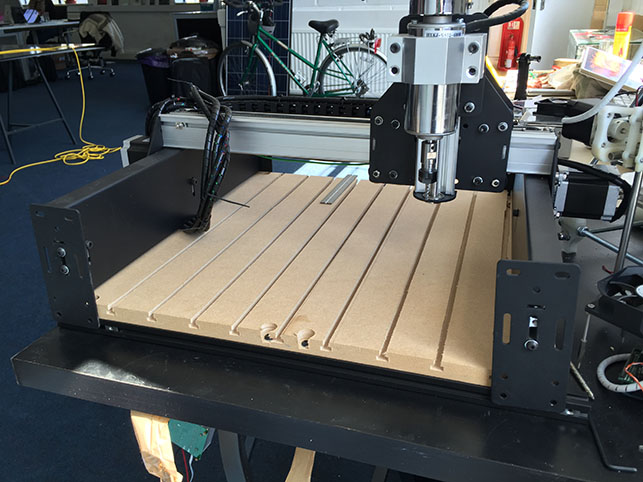
I have been using my Shapeoko on an off over the past few months and the most frustrating thing is clamping. Nothing is more annoying when you have perfectly aligned it and your clamp or screw moves and it all goes off! Best option is a surface that can be clamped to. I have seen other people try solutions like putting in nail nuts to the surface or just buying a pre-made aluminium clamp bed (£££). But I wasn't to sure about it, especially if as I have found my mill losses grip on the bit and it plunges right down I didn't want to collide with steel. I found a special router bit that lets you cut undercut grooves into wood so you can put bolt heads into it. Pictured above is it fitted to the Shapeoko and was quite easy to make (lots of dust though!)
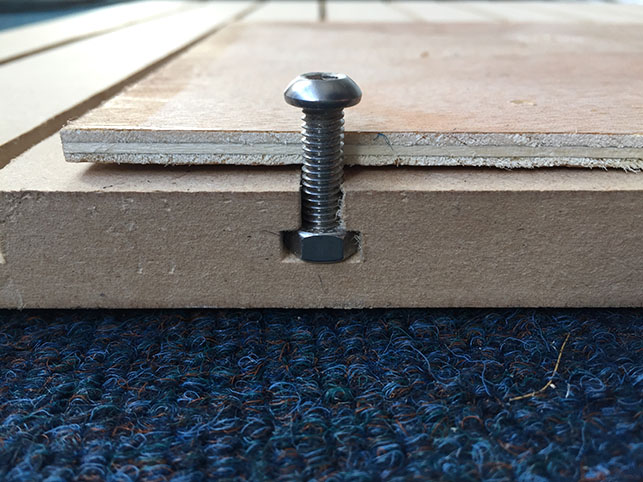
This seemed good as all I need is a cheap bit of MDF cut to size and then I can just route a grid of clamp groves. If I accidentally over cut it also doesn't matter as I can just make up another table when it is trashed. So it is like a waste board clamp table!
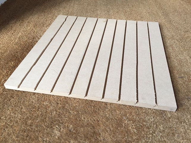
My router slipped a little when I was cutting it as the guide is awful, I had to switch to using a bar of wood as a rail. It doesn't matter though, just looks ugly! Then I just used the supplied waste board as a guide for the bolt holes to bolt it into the frames. Next I will be making some clamps with the Shapeoko!
Page 2 of 10