Blog
Posts 11–15 of 47
Page 3 of 10
VGA cap
16 January 2016 · Open this post on its own
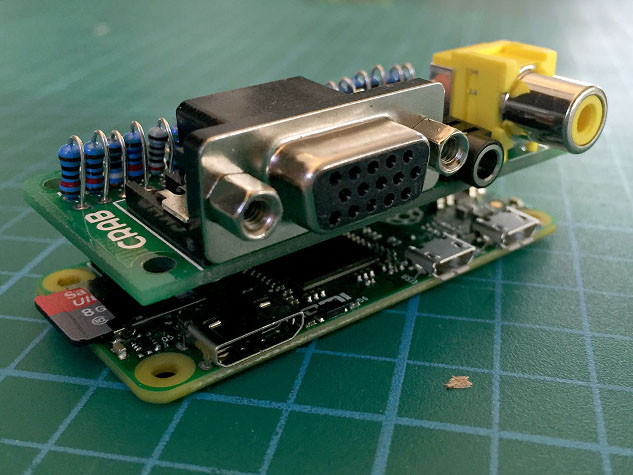
Here is a PCB I have designed, it was made in response to the release of the Raspberry Pi Zero. For a low cost it helps to break out the analogue outputs from the zero. The analogue ports it provides are stereo audio, composite and VGA. This is all on the same edge as the Zero's existing connectors. This board is ideal if you want to utilize a computer monitor, especially if it has built in speakers like many 'multimedia' TFT screens that now cost very little second hand. Apart from the composite output it will also work on any Raspberry Pi that has the 40 pin GPIO header (Raspberry Pi A/B+ and the Raspberry Pi 2) I am fund raising to make a bunch of them on Kickstarter see here
It is a kit
To make it as cheap as possible and easy to adapt for different purposes it is a kit / bare PCB that uses only through-hole components. Due to a lack of space all components are folded this may make it a little fiddly to construct if you have less experience but it is not too hard.
What this means though is that you can choose which way up the cap is mounted, if you what the VGA or not and if you are building into an enclosure the pads can be directly soldered.
Enabling the outputs
Full instructions can be found on crab.design
Due to space and cost the cap does not have auto configuration EEPROM as defined by the HAT specification. It has to be set up by editing the config.txt and adding files to the /boot/ partition.
For VGA it uses Gert van loos VGA666 circuit which uses a passive resistor network to perform the Digital to Analogue conversion. The pins it uses are slightly different to allow for the audio to also be broken out of the GPIO header. To activate VGA an 'overlay' has to be added to the configuration files of the boot partition. These will be provided in the Github repository.
Analogue audio is the same as the circuit on the Raspberry Pi B+ schematic, but instead the output comes from the GPIO. To activate another 'overlay' is used that comes with the default Rasbian distribution (pwm-2chan-overlay) If this and the VGA is activated only 4 GPIO pins will remain.
The composite is simply an extension of the new breakout pins next to the the Zero's GPIO header, it is connected by its own socket when the cap is pushed on.
The parts activated are up to the user by simply disabling and enabling parts in the config.txt file. More information will be up soon at the crab github pages.
What is crab?
Crab is going to be a series of circuits that I think are useful repeatable modules for use in installations. That is not strict though, I am also designing circuits and boards that can inspire ideas and teach that may not be so practical.
CAD with code (OpenSCAD)
16 January 2016 · Open this post on its own
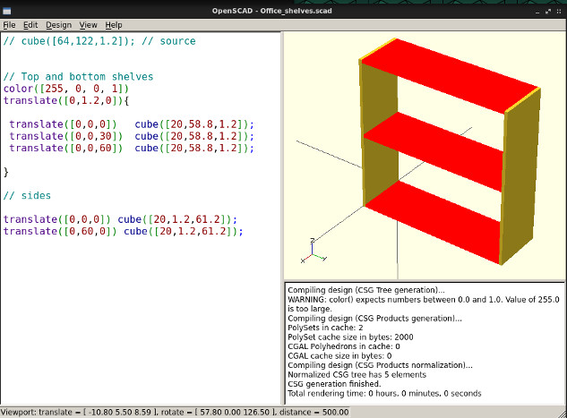
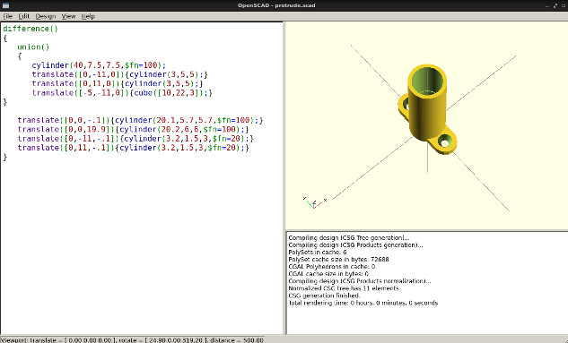
If you like to think in code this CAD program is great, especially if the design can be broken down into primitives. This is an example of a very basic shelf I designed but I have been using it for everything from designing mounts to hold PIR sensors to a shed that will become the new Clacktronics workshop!
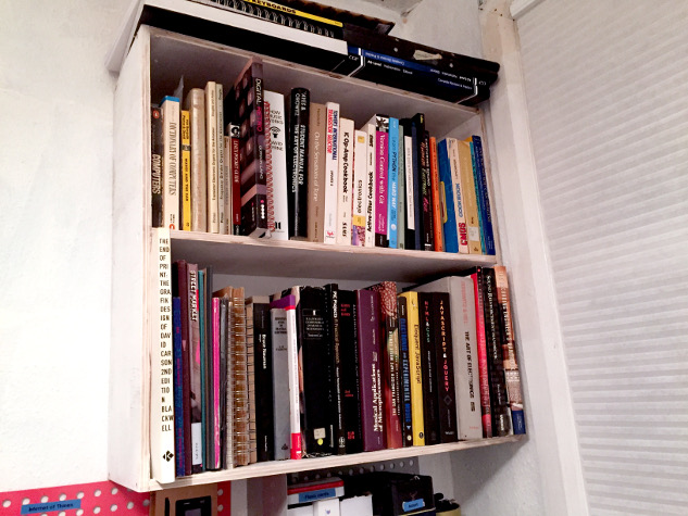
The interesting thing is that you end up with segments of code that can represent the real life segments you need to cut to construct your design. Even better if doing something more complicated you can make it parametric by using variables and even iteration.
I have done slightly more complicated tasks with it apart from shelving! Here is an example of a job I did where I used mini PIR sensors in 3d printed mounts so they could be used to detect human movement but on a narrow beam.
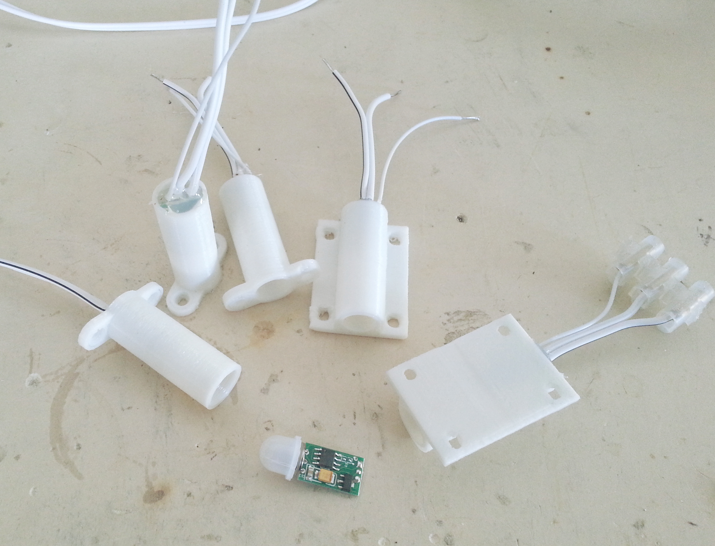
The PCB slotted perfectly into the mount and was held in with hot glue. Details for this project can be found on the Clacktronics Github page.
Colours, Speakers and Pulses
13 January 2016 · Open this post on its own
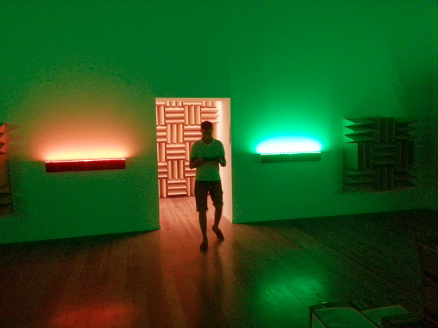
This is a story about what I currently do, I have moved a little bit away from synthesizers but still make audio electronics for artist Haroon Mirza and sometimes other artists. The approach to making artworks are different to designing audio devices, as usually components and circuits are one-off designs or modified items which are usually used against their original intention. The reason I decided to write about this was to document how the system works for this particular work as it is using new technologies that are getting easier to prototype with. I am really impressed with this new microcontroller implementation of Python programming language called Micro Python.
Courtesy the Tinguely Museum, Switzerland
Background
Channa Horowitz . was an American artist who came up with a system called 'Sonakinatography' which is a compound word of sound, motion and notation. According to Wikipedia the system was part of a proposal for a sculpture that she sadly never got to produce, she did produce drawings for the works and although they are scores for works they actually became 'artworks'.
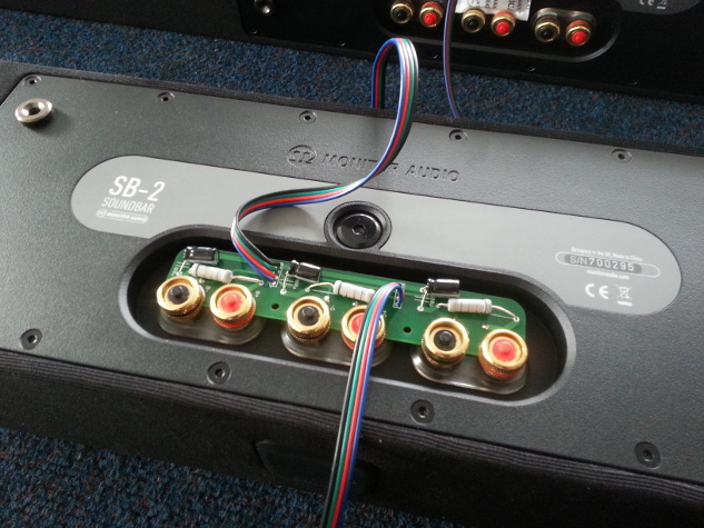
I am not sure if I am allowed to post a photo of an artwork but if you search Sonakinatography in your favourite search engine you will see the drawings. The way the work was interpreted is that each horizontal line of Channa Horowitz's work is treated as a step, like a step sequencer this is fed to 8 RGB LED strips that each sit on top of a 3 channel sound bar (the speakers for TVs). The PWM control of the Red, Green and Blue is also fed into the 3 internal speaker cones od the sound bar ; so left speaker is red, middle green and right is blue.
Better Specs
For ages we had been using Arduinos and burning PICs to playback sequences but they had hit memory limits. This was temporarily helped by storing sequences as byte arrays (smaller than integers) and using an Arduino Mega with larger flash memory but as longer and longer sequences were used the devices kept running out of space. Channa Horowitz's work is up to 4000 lines so this would definitely overflow the memory! The only solution for this was to use external memory, ideally I thought was to use a memory card to make it easier to change sequences.
There also was a new requirement, for this new work it needed to drive 8 x RGB leds this means we would need a device to output 24 independent channels this is beyond the Arduino Mega alone. At first I investigated using serial controlled PWM devices such as the SPI controlled TLC5947 but a requirement was that each channel could have its own pitch, something not typically a concern of a PWM controller. Then I remembered I had recently acquired a microcontroller device a bit like Arduino called a PyBoard which is designed to run MicroPython as I mentioned earlier. Sadly it only could handle 20 channels, but surely it could do more! so I asked on the forum (http://forum.micropython.org/viewtopic.php?t=497) and surely enough Damien (who created both the language and the board ) showed me how to kludge 4 extra channels out of it.
The Program
Because Micro Python is very close to Python 3 it was very easy to prototype the program, after initial difficulties of getting all the PWM channels to work and reporting some bugs to Micro Python repository ( which get fixed fantastically fast! ) it was a breeze to prototype the program. As it is Python I could use regular expressions to parse text files this means that the sequences could be human readable (and forgive human error in coding the files) with no need for brackets or other types of programming syntax. The program simply reads the text files line by line and outputs it straight to the LEDs with no noticeable delay! As it is not 8bit but a 32bit ARM another amazing feature was that I could set the pitch of the channels to almost any frequency.
The Circuit
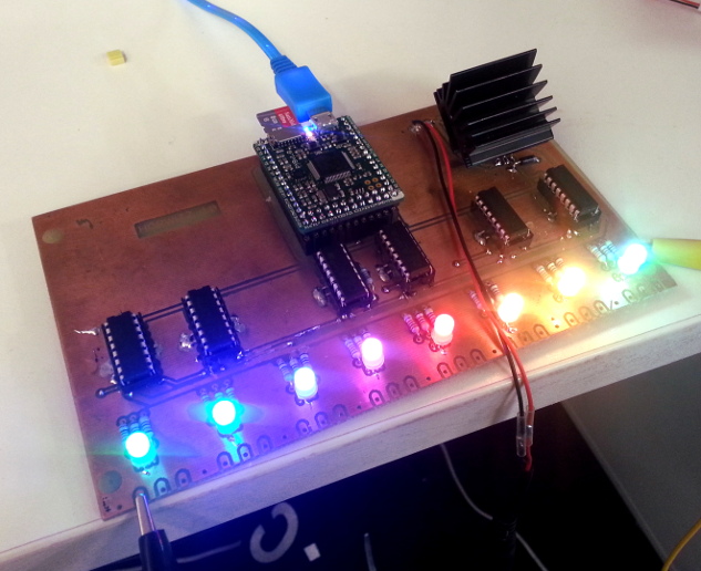
The circuit was a little bit different to what I used before, usually I use MOSFETs to drive LED strips, by connecting them to ground. But for this circuit as each LED was also driving a speaker I thought maybe I would try a little less conventional component. I used the L293 H-bridge driver which is typically used for driving stepper motors and relays but as a speaker is quite similar I thought it should be suitable! it also had the added bonus of being able to drive current bi-directionally so I could drive common cathode or common anode LEDs without changing the circuit much. (this is done very simply with a jumper on the PCB ).
Now directly driving speakers with DC PWM works fine but it uses a lot of power which is fairly wasteful and unnecessary so I created a circuit that reduces the power with a limiting resistor and also removes DC with a cap, it also has diodes to prevent inductive kickback from the speakers.
Designing the board
At first I designed the board to be as tight as possible, but this was a complete mess, routes became very long and I had gangs of tracks adding big borders around the board, I found it much better to lay it out a little more spaced. It made the board quite large, it is a bit bigger than a euro card but much cleaner. Using the Press n Peel method I created a double sided mockup of the board, this was actually used in media images of the show! For the connections to the speakers I went for 3.5mm pluggable terminal blocks, these are great.
The speaker circuits were directly attached to the back of the speaker, I designed a PCB that could be clamped on the terminals of the speaker, this made it very convenient and made it easy to split the signal to the LED and the speakers. It is very important to limit the amount of wiring in installations as the more wiring the more likely they can snag and break!
Enclosing
Only issue with using terminal blocks is that they need square holes, for speed I decided to get a box lazercut this also allowed me to put markings on it and cutout a fan for a hole.
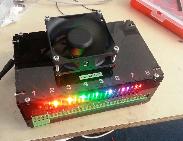
The Enclosure
Wanted - 'Tympani' or 'lo Tom' info
25 March 2015 · Open this post on its own
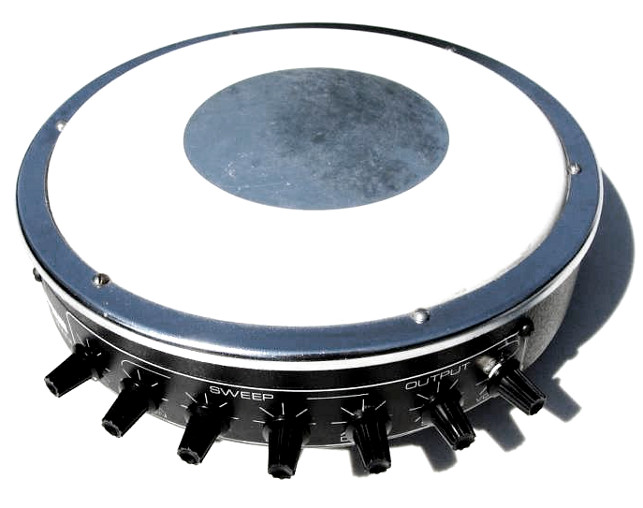
Clacktronics is trying to improve the Analogue drum lab and I am looking for information about them. This could be in schematic in repair manual form ( might possibly be none existent ) or perhaps you own a unit? Even if it is broken I am interested, I will repair if for free! Otherwise I am even interested if all you can provide is photograph of the PCB top and bottom. This is also a notice that lots of new information will be uploaded soon to the drum lab!
Star Instruments created some very interesting designs in the mid-70's until the 80's. Because of when they were designed ( an probably on a budget ) many of the parts are quite basic and off the shelf rather than the bespoke chip Roland drum machines you see. Luckily that means quite a lot of the parts are still available today such as OTA's and CMOS chips. Which makes them perfect material for re-construction and analysis.
The Sounds are quite typical but get interesting when the pitch is pushed right down.
Casting expanded polystyrene
18 March 2015 · Open this post on its own
I am currently designing a small desktop rotating speaker, it is basically a miniature version of a rotating polystyrene Leslie baffle that is found in the guts of a cheap 70's electric organ. I will show some results of this soon but first I want to share an idea about how to DIY mould polystyrene.
To make maquettes of the design I have been using 3d printed PLA shapes, I can produce them quite lightweight as 3d printing allows me to them very hollow, but I couldn't help wondering how to make a polystyrene one. Especially as I think polystyrene is probably more dampening to sound which is ideal for this device that I am making. As a bonus it is also used for the original speaker. I have a CNC so I could carve it out of a machinable foam ( expanded polystyrene is a bit tricky! ) but looking at polystyrene packaging I noticed it is actually moulded in a very similar way to injection moulding.
So what is expanded polystyrene?
Polystyrene is a plastic, basic polystyrene is a pretty hard and brittle, CD jewel cases are typically made from various types of polystyrene. So actually what most people think of as polystyrene is expanded polystyrene (EPS) this is polystyrene that has been made into pellets then aerated and expanded many times its volume. That makes it very lightweight and a great insulator! downside is that it is pretty flammable, so if it is used in building insulation you have to make sure it is flame retarded.
How to cast with it
But how are shapes formed with these pellets? I initially thought that perhaps a machine somehow pushes the beads into a space then compresses it under heat, but experiments with heating a bead or two up showed me they just dissolve back to their original density! Information on the factory process is pretty scarce so after a bit of searching I found this small explanation below of the entire process.
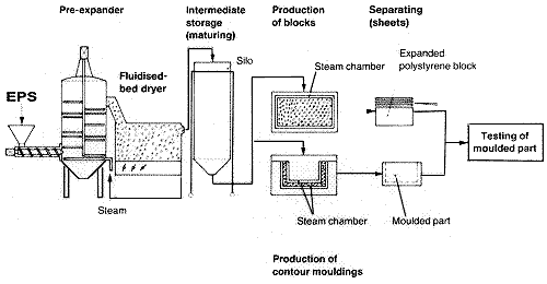
EPS is manufactured from styrene monomer, derivative of ethylene and benzene, using a polymerisation process which produces translucent spherical beads of polystyrene, about the size of sugar granules. During this process a low boiling point hydrocarbon, usually pentane gas, is added to the material to assist expansion during subsequent processing. Beads are delivered to EPS processors usually in boxes of 600kg or 1000kg.
EPS is produced in a three stage process. In the first stage, polystyrene beads are expanded to between 40 and 50 times their original volume by heating to about 100ºC with steam in an enclosed vessel called a pre expander. During this process the beads are stirred continuously. In this process the final density of EPS is determined. This is typically between 14 kg per cubic metre and 30 kg per cubic metre. After pre expansion, the expanded beads are cooled and dried in a fluidised bed drier, before being pneumatically conveyed to storage silos for maturing.
During maturing, the second stage of processing, the expanded beads containing up to 90% air are stabilised typically over a period of 24 hours. Following pre-expansion, the beads have a partial vacuum which must be equalised before final processing by allowing air to diffuse into the beads until equilibrium is reached.
In the third stage of processing, known as the moulding stage, beads are conveyed into a mould, and once in the mould are heated again by the introduction of steam. Under the influence of steam, the beads soften and start to expand again. However, as they are contained in a mould they cannot expand freely, and therefore create an internal pressure within the mould. Under this pressure the softened beads fuse together when the correct temperature is reached within the mould. Following fusion the mould is cooled, usually under the influence of a vacuum to remove moisture. The moulded product is ejected from the mould at the completion of the cycle. During processing, the pentane gas is expended, so that the finished products contain no residual gas.
There are generally two moulding processes for EPS. One is called Block Moulding and produces large blocks of EPS up to 5 metres in length. These are subsequently cut into shapes or sheets for use predominantly in packaging and in construction.
The second moulding process is known as Shape Moulding, and produces shaped parts ready to use in a wide range of applications. Electronic product packaging in particular is where shape moulded EPS is used extensively. Computers, office machines, televisions and stereo equipment are everyday examples.
Source www.plastics.org.nz
So it mentions that there are 2 stages, making the beads and casting the beads. There is no chance I have the ability to process my own polystyrene into EPS, but what if I can get hold of the secondary material? All that seems to happen is steam is injected into a mould, that can't be hard to re-create! Looking at various Alibaba listings for raw EPS I noticed that the beads sold for straight casting look pretty much like the ones sold for filling bean bags. Could it be that manufacturers just buy pre cast raw EPS and fill bean bags with it? maybe, but perhaps they post-expand the beads for maximum volume and cost? Time for an experiment. I purchased a small bag of EPS beads from ebay, specifically 'virgin' beads ( horrible name ) that means they are not recycled broken down cast polystyrene but perhaps straight from the first process?
Experiments
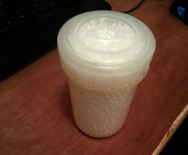
To simulate the casting process I used the following
Wall paper steamer
water tight Tupperware container
'virgin' bean bag beads
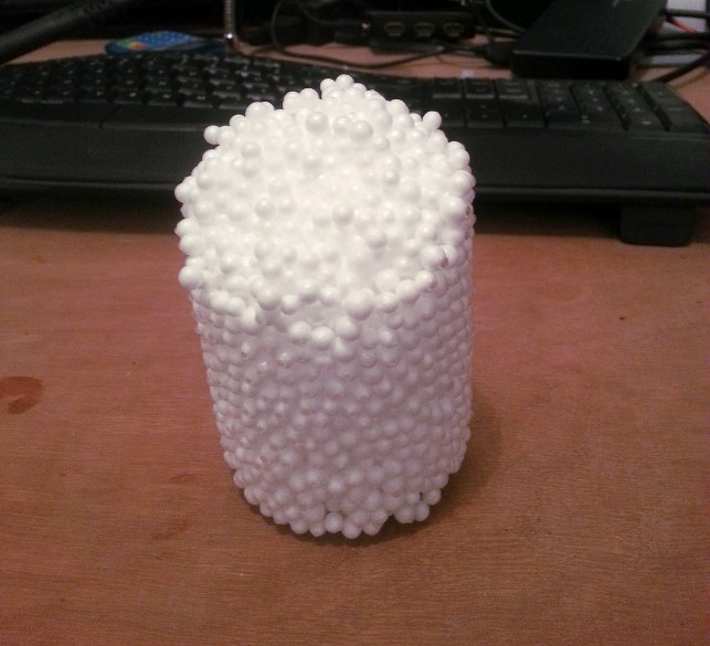
Test 1
======
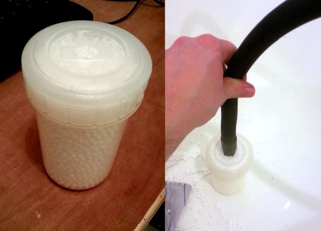
I drilled a hole in the top of the container and filled it with the beads all the way to the top.
Then I waited for the wallpaper steamer to heat up, once to temperature I put it on the hole trying not to scald myself
Success! it held together, well sort of. It didn't really expand tightly to the sides and only half of it cast, it also breaks apart quite easily. So I thought perhaps I need to drill holes in the bottom to let the steam flow through and not cool and compress more beads inside when I load it up.
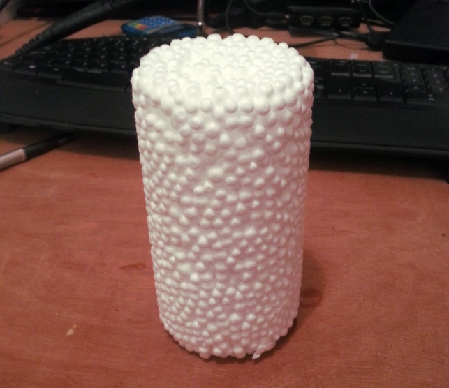
Test 2
======
I drilled holes in the bottom and compressed more beads inside, I also held the steam on for a lot longer. This worked a lot better and I got a solid shape, it still did not cast flat to the surface and water flows right through it , so it is not closed cell like commercial packaging. But this is a lot better and process perhaps I can create a process to mould EPS into shapes.
How can I improve and go further
Thats the end of my experiment for tonight, but I am interested into how to take this further, here are my further research points.
Looking at moulding stage explanation of Plastics.org.nz I notice it mentions a vacuum perhaps this may help expansion or maybe it just to remove water
Perhaps my steamer is not hot enough, I will test it with a thermometer
The EPS material is almost max-expanded, I see a lot of different grades of polystyrene on Ebay, there may be a better one.
Moulding, how to create a device to allow me to make moulds, it may not need to be metal as temperatures are fairly low, perhaps a high temp plastic might work?
Page 3 of 10